
Reversible cable tie

a cable tie and reverse technology, applied in the field of cable tie, can solve the problems of inconvenient disassembly procedure of conventional tie and the inability to abandon whole tie, and achieve the effect of convenient operation, convenient re-use application, and convenient structur

Inactive Publication Date: 2014-06-19
WISTRON CORP
View PDF3 Cites 19 Cited by
  • Summary
  • Abstract
  • Description
  • Claims
  • Application Information

AI Technical Summary

Benefits of technology

The present invention is a reversible cable tie that allows for easy and secure constraint of a belt or other structure. It features a hook that can be pulled to quickly separate the belt from its constraint base, while the belt remains free to move inside. The tightness of the cable tie can be adjusted to remove external force and allow for tight and stable constraint. Compared to previous designs, the reversible cable tie is easy to use and can be re-used.

Problems solved by technology

Therefore, disassembly procedure of the conventional tie is inconvenient due to separation of the sawtooth structures and the engaging units.
The second engaging portion can not be separated from the first engaging portion if tightness of the conventional tie is insufficient, and the whole tie is useless to be abandoned.
Thus, the conventional tie is environment-unfriendly style, and design of a reversible cable tie is an important issue in the related industry.

Method used


Image

  • Reversible cable tie
  • Reversible cable tie
  • Reversible cable tie

Examples


Embodiment Construction

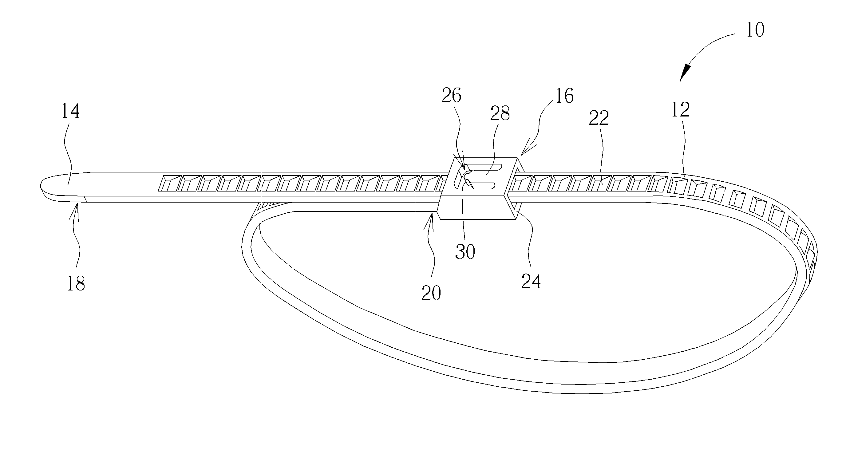
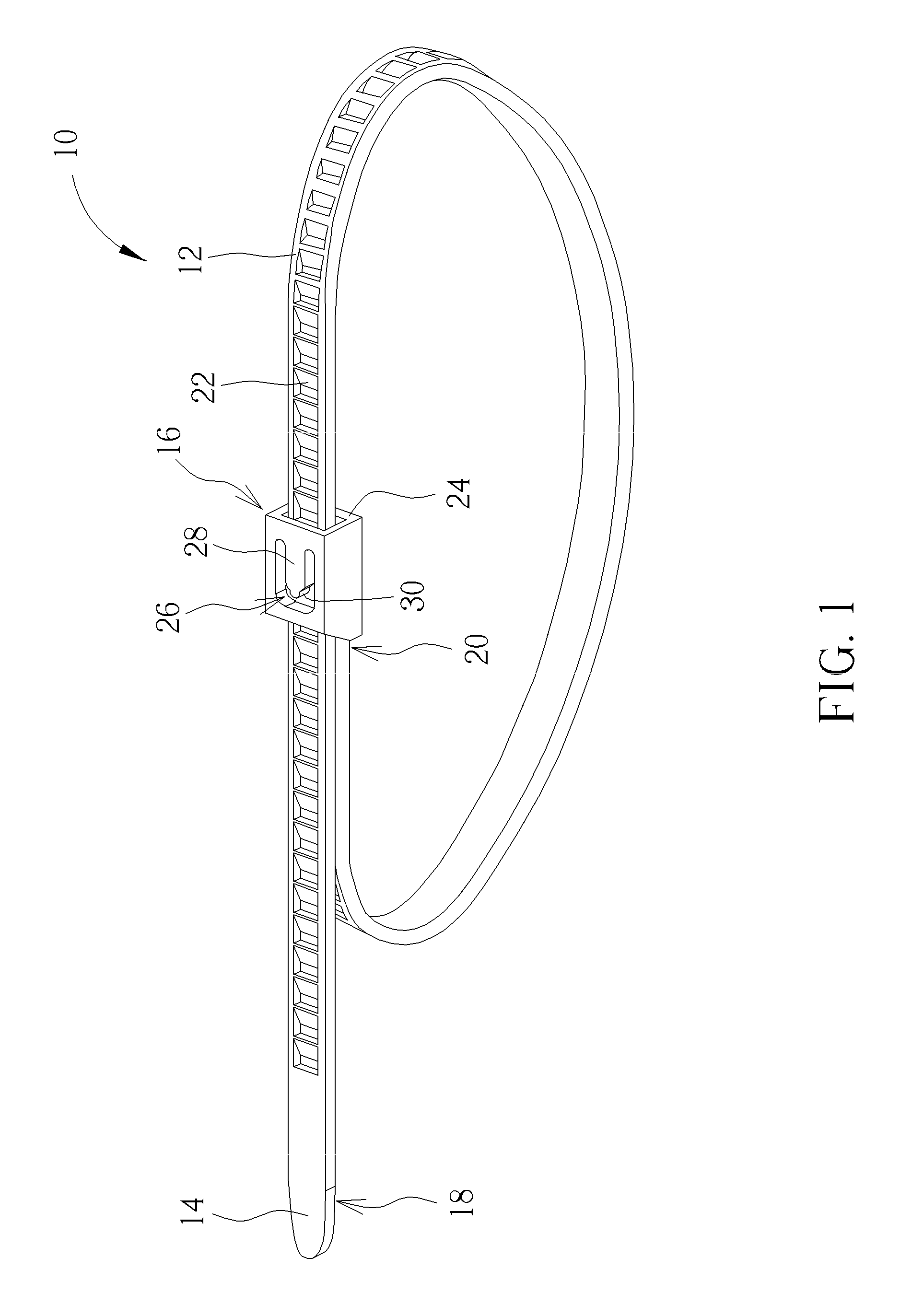
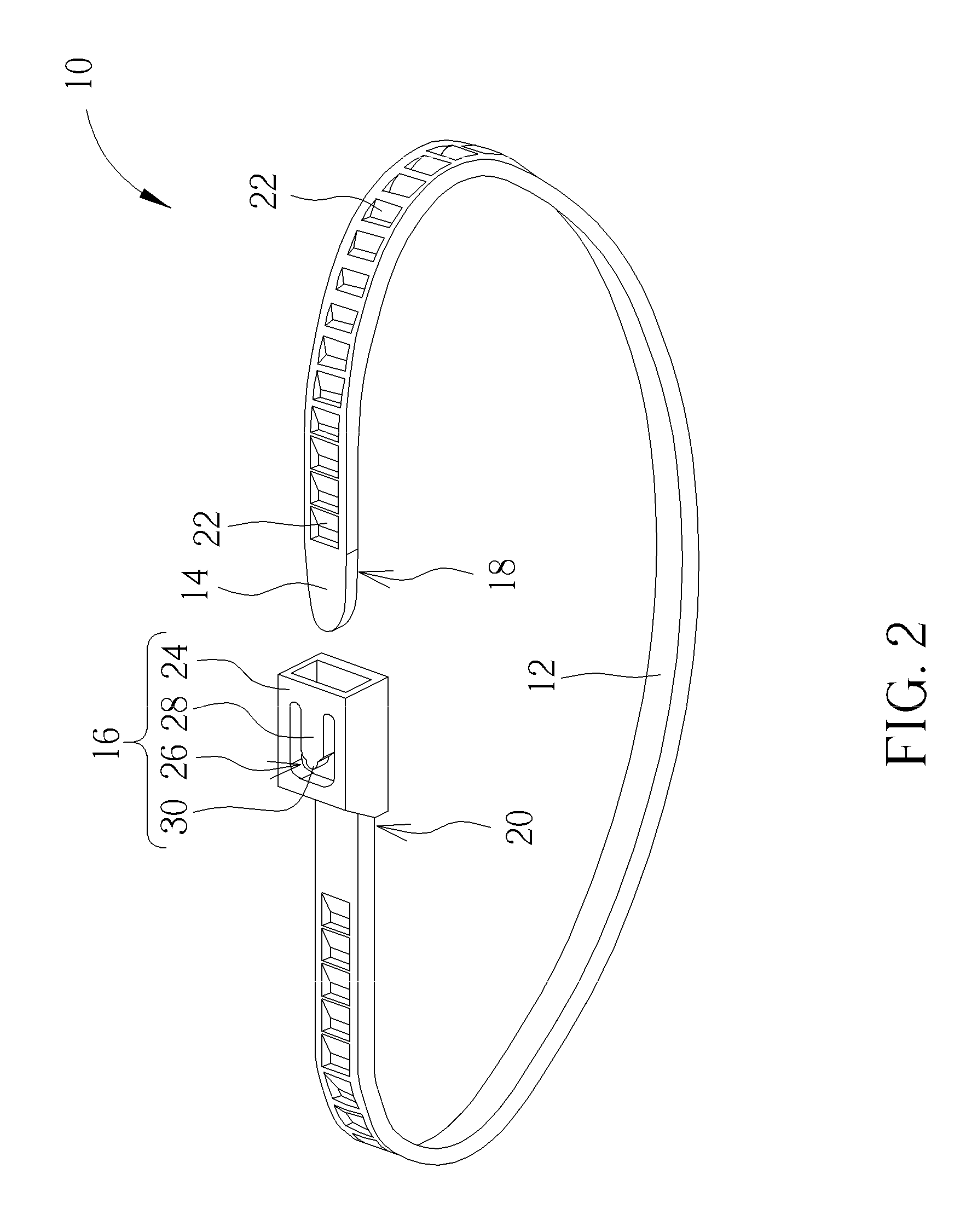
[0020]Please refer to FIG. 1 and FIG. 2. FIG. 1 and FIG. 2 respectively are diagrams of a reversible cable tie 10 in different operation modes according to an embodiment of the present invention. The reversible cable tie 10 includes a belt 12, a guide portion 14 and a constraint base 16. The belt 12 can include a first end 18, a second end 20 and a plurality of constraint structures 22. The first end 18 and the second end 20 are opposite ends of the belt 12. The plurality of constraint structures 22 is disposed between the first end 18 and the second end 20. In addition, the guide portion 14 is disposed on the first end 18, and the constraint base 16 is disposed on the second end 20. The guide portion 14 can be driven to pass through the constraint base 16, and the constraint structure 22 of the belt 12 is engaged inside the constraint base 16, so as to tie up an object firmly by the reversible cable tie.

[0021]Please refer to FIG. 3 and FIG. 4. FIG. 3 and FIG. 4 respectively are dia...


PUM


Abstract

A reversible cable tie includes a belt, a guide portion and a constraint base. The belt includes a first end, a second end and a plurality of constraint structures. The guide portion and the constraint base are disposed on the first end and the second of the belt. The constraint base includes a hollow portion, an opening structure, a hook and a handle. The belt passes through the hollow portion. The opening structure is disposed on an external surface of the hollow portion. The hook is movably disposed inside the hollow portion and exposed via the opening structure. A first end of the hook is resiliently connected to a first wall of the opening structure. A second end of the hook buckles the constraint structure, so as to constrain a movement of the belt relative to the constraint base. The handle is disposed on the second end of the hook.

Description

BACKGROUND OF THE INVENTION[0001]1. Field of the Invention[0002]The present invention relates to a cable tie, and more particularly, to a reversible cable tie.[0003]2. Description of the Prior Art[0004]The tie is often applied to bind the object, such as wires, rods and so on. The conventional tie includes a body, a guide portion and a constraint base. The guide portion and the constraint base are respectively disposed on two ends of the body. A plurality of first engaging portions is disposed on a surface of the body, and a second engaging portion is disposed inside the constraint base. When the guide portion guides the body through the constraint base, the second engaging portion can be engaged with the first engaging portion for constraint between the body and the constraint base to bind the object.[0005]The conventional tie includes the second engaging portion with sawtooth form that is disposed inside the constraint base, and the sawtooth-shaped second engaging portion includes...

Claims


Application Information

Patent Timeline
IPC IPC(8): B65D63/10
CPCB65D63/1081B65D63/1072B65D2563/107Y10T24/1498Y02W30/80
Inventor YUAN, JIA
Owner WISTRON CORP
Learn More