
Sheet processing apparatus and image forming apparatus

a technology of image forming apparatus and processing apparatus, which is applied in the direction of electrographic process apparatus, printing, instruments, etc., can solve the problems of extremely orthogonal drop in fastening power, and extremely low fastening power

Active Publication Date: 2014-06-12
CANON KK
View PDF7 Cites 28 Cited by
  • Summary
  • Abstract
  • Description
  • Claims
  • Application Information

AI Technical Summary

Benefits of technology

The present invention relates to a sheet processing apparatus that can stack and bind sheets. It includes a sheet stacking portion and a sheet binding unit with two sets of concavo-convex binding teeth. The sheet binding unit can perform a binding process by forming a bundle of sheets with the binding teeth and then selectively either biting the edges or the center of the bundle. This allows for either a strong binding or a weaker binding mode. The apparatus also includes a positioning mechanism that can change the relative position of the sheet binding unit and the sheet bundle for better binding. This invention improves the efficiency and accuracy of sheet processing.

Problems solved by technology

However, the sheet processing apparatus described above configured to fasten the sheet bundle by biting the sheet bundle by the concavo-convex teeth has a drawback that although the sheet processing apparatus endows the sheet bundle with a predetermined fastening power in a direction in which the fibers are entangled, the fastening power drops extremely in a direction orthogonal to the direction in which the fibers are entangled.
The sheet processing apparatus also has another drawback that it can fasten the sheets only with an extremely low fastening power in fastening the sheet bundle by entangling the fibers if moisture of the sheets is low or smoothness of surfaces of the sheets is high and it is hard to entangle the fibers with each other.

Method used


Image

  • Sheet processing apparatus and image forming apparatus
  • Sheet processing apparatus and image forming apparatus
  • Sheet processing apparatus and image forming apparatus

Examples


Embodiment Construction

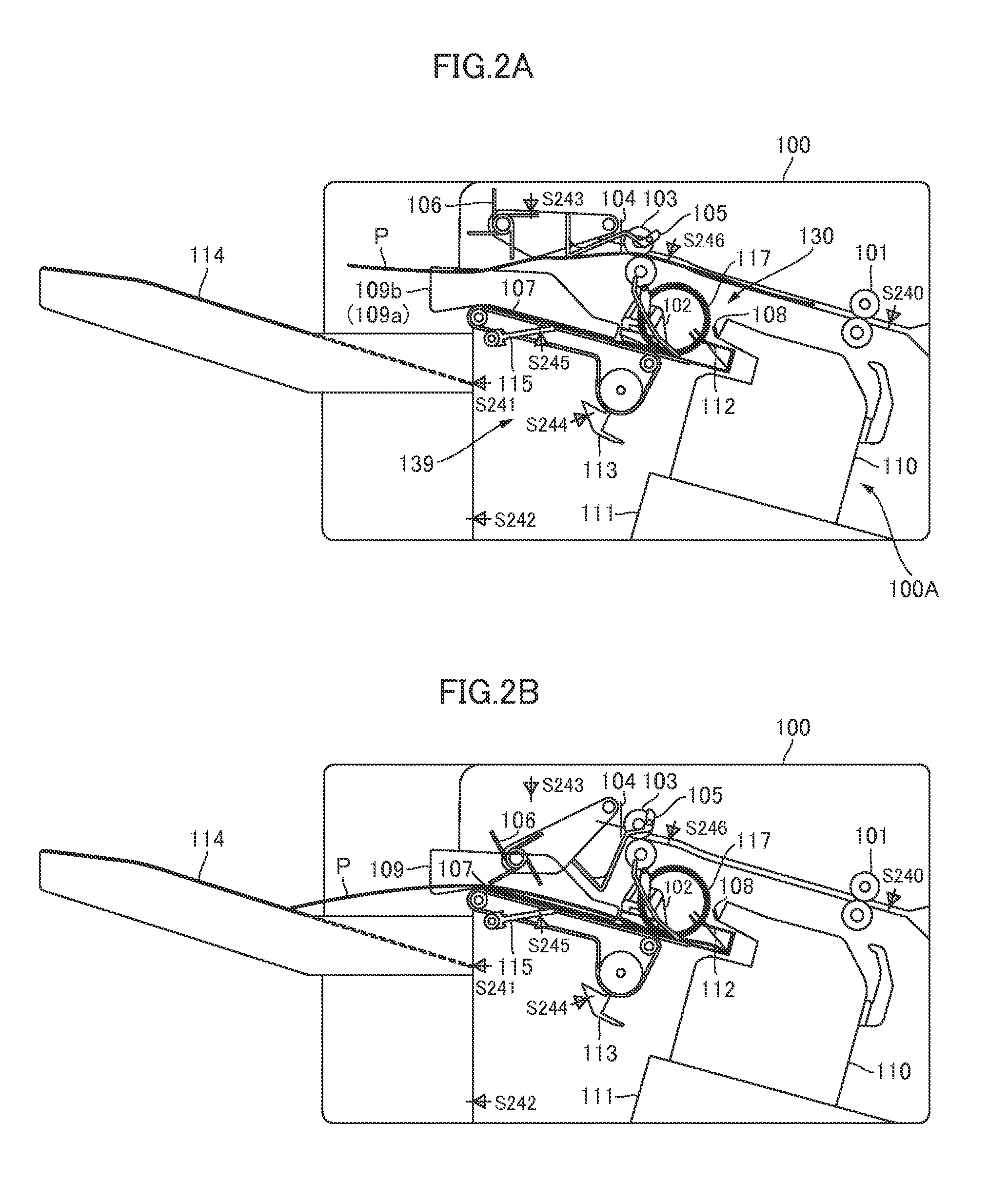
[0034]Embodiments for carrying out the present invention will be detailed below with reference to the drawings. FIG. 1 is a diagram illustrating a configuration of an image forming apparatus provided with a sheet processing apparatus of the embodiment of the invention. As shown in FIG. 1, the image forming apparatus 900 includes a body of the image forming apparatus (referred to as an “apparatus body” hereinafter) 900A, an image forming portion 900B configured to form an image on a sheet, an image reading apparatus 950 provided at an upper part of the apparatus body 900A and provided with a document feeder 950A, and a sheet processing apparatus, i.e., a finisher 100, disposed between an upper surface of the apparatus body 900A and the image reading apparatus 950.

[0035]The image forming portion 900B includes photoconductive drums (a) through (d) configured to form toner images of four colors of yellow, magenta, cyan and black, and an exposure unit 906 configured to form electrostatic...


PUM

PropertyMeasurementUnit
Widthaaaaaaaaaa
Areaaaaaaaaaaa
Surface smoothnessaaaaaaaaaa

Abstract

A staple-less binding unit including a pair of upper and lower teeth binds a sheet bundle which is discharged to an intermediate processing tray by a sheet discharge portion and whose one edge abuts against a rear edge stopper. A control portion switches a binding mode of the staple-less binding unit that implements the binding process on the sheet bundle in a first binding mode of binding the sheet bundle without any staple such that the pair of upper and lower teeth bite across an edge of the sheet bundle and in a second binding mode of binding the sheet bundle without any staple such that the pair of upper and lower teeth do not bite across any edge of the sheet bundle.

Description

BACKGROUND OF THE INVENTION[0001]1. Field of the Invention[0002]The present invention relates to a sheet processing apparatus configured to bind a bundle of sheets and an image forming apparatus including the same.[0003]2. Description of the Related Art[0004]Hitherto, some image forming apparatuses such as a copier, a laser beam printer, a facsimile machine, and a multi-function printer are provided with a sheet processing apparatus configured to perform such processes as stapling on sheets on which images have been formed. Such a sheet processing apparatus is configured to bind a bundle of sheets by using a metallic staple in general. Lately, however, as another method for binding sheets, there is proposed a method of fastening a sheet bundle without using any metallic staple by considering environmental issues by entangling fibers of the sheets by biting the sheet bundle by concavo-convex teeth and forming concavo-convex dents on the sheets as disclosed in Japanese Patent Applicat...

Claims


Application Information

Patent Timeline
IPC IPC(8): B42B5/00
CPCB42B5/00B42C5/00B31F5/02B31F2201/0754B42B4/00B42F3/003B65H2301/51616G03G2215/00852
Inventor OBUCHI, YUSUKEABE, HIDETO
Owner CANON KK
Learn More