
Backlight module and display device

a backlight module and display device technology, applied in the field of backlight modules and display devices, can solve the problems of unsatisfactory light intensity, inability to solve, and easy to cause hot spots

Active Publication Date: 2014-06-12
BOE TECH GRP CO LTD +1
View PDF20 Cites 7 Cited by
  • Summary
  • Abstract
  • Description
  • Claims
  • Application Information

AI Technical Summary

Benefits of technology

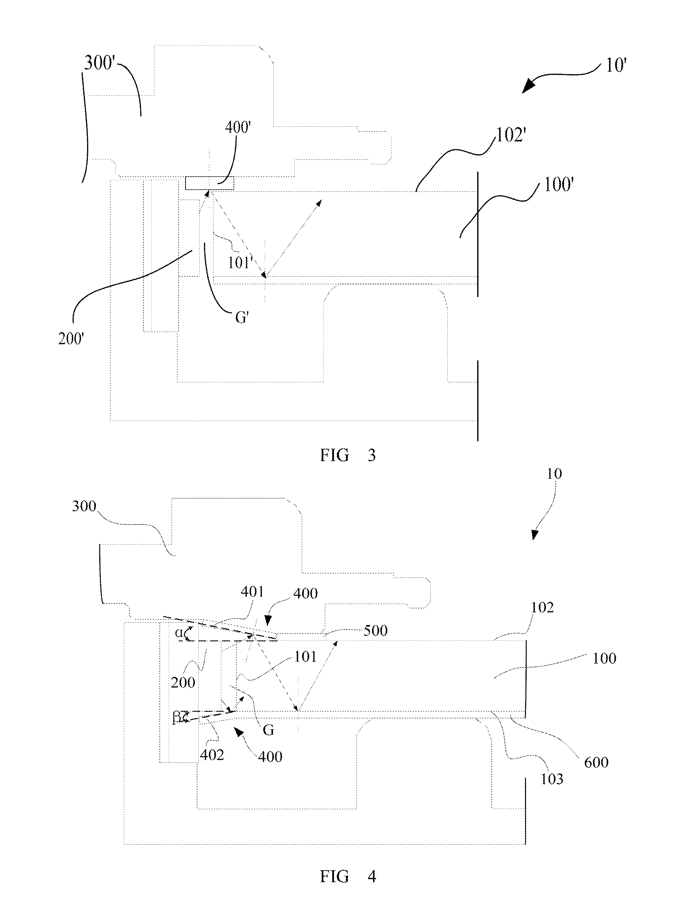
The present invention is a backlight module that improves the utilization rate of the light source and reduces hot spots. It achieves even light intensity and meets the requirement of a large gap between the LED light bar and the light guide plate in terms of thermology. The reflection member is arranged outside the gap between the LED light bar and the light guide plate to improve the utilization rate of the light source. Position of each first region corresponds to a position of each LED lamp, and a position of each second region corresponds to a position between two adjacent LED lamps or a position outside of the LED lamps on the end of the LED light bar. The first region has a reflective index less than the second region to reflect the light at the intervals between the LED lamps and / or outside the LED lamps at the end of the LED light bar to the light guide plate as much as possible.

Problems solved by technology

As a result, an uneven light intensity will be achieved and hot spots will easily be caused.
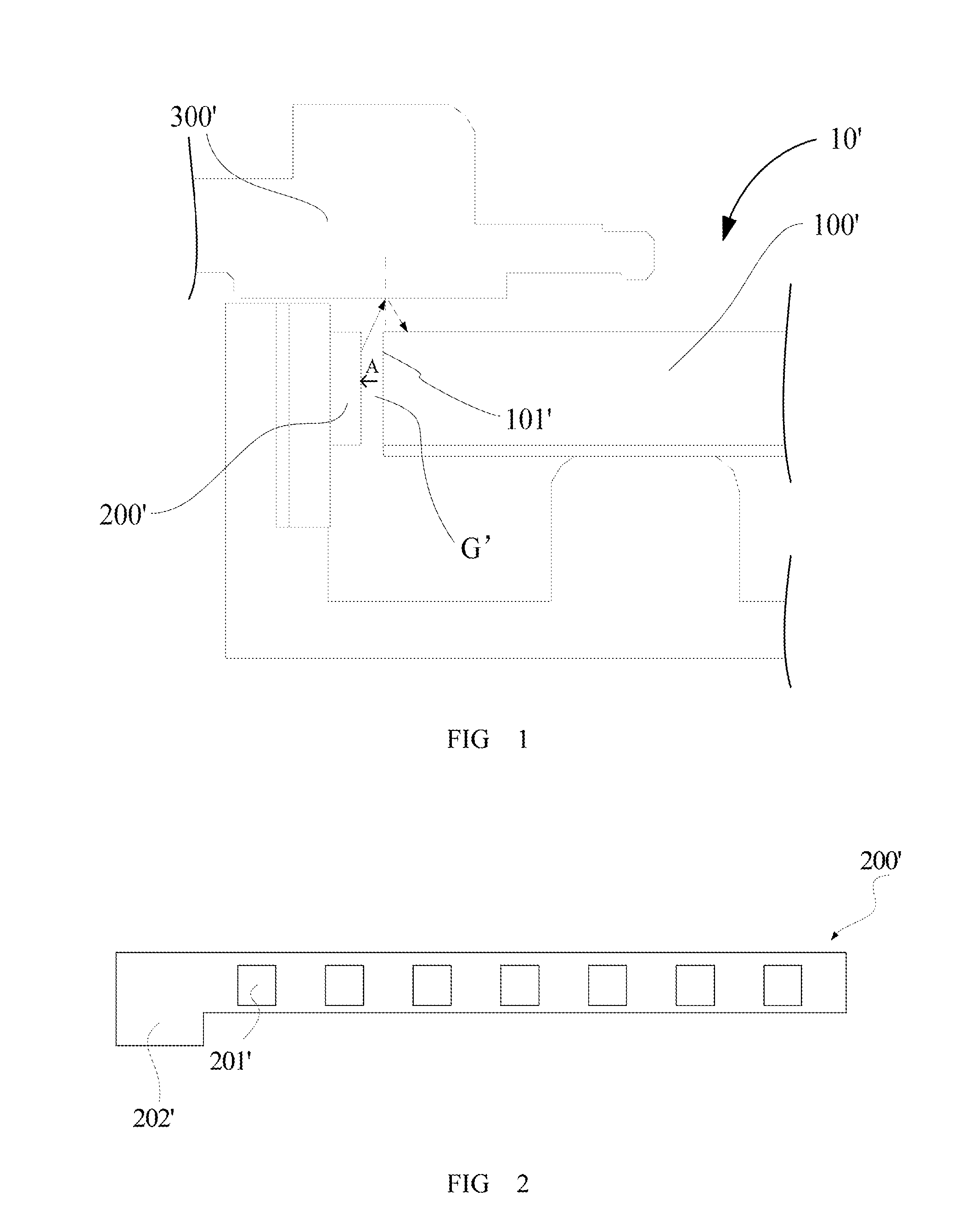
However, such a structure, on one hand, cannot solve the problem of uneven light intensity due to the distribution of the LED lamps at intervals as well as the hot spots generated thereby, and on the other hand, cannot solve the problem of light loss due to the escape of a part of the light from the slit between the reflector 400′ and the light guide plate 100′.

Method used


Image

  • Backlight module and display device
  • Backlight module and display device
  • Backlight module and display device

Examples


Embodiment Construction

[0028]To make the objects, the technical solutions and the advantages of the present invention more apparent, the present invention will be described hereinafter in conjunction with the drawings and the embodiments.

[0029]FIG. 4 is a side schematic view of a backlight module according to one embodiment of the present invention. As shown in FIG. 4, the backlight module comprises a light guide plate 100 including a light-entering surface 101, a light-exiting surface 102 adjacent to the light-entering surface 101, and a back surface 103 opposite to the light-exiting surface 102.

[0030]FIG. 5 is a schematic view showing the positional relationship between a reflection member and a LED light bar in the backlight module according to one embodiment of the present invention. As shown in FIG. 5, the LED light bar 200 includes a PCB 202 and a plurality of LED lamps 201 arranged at intervals. The LED light bar 200 is arranged at a side opposite to the light-entering surface 101 of the light guid...


PUM


Abstract

A backlight module and a display device comprise: a light guide plate; a LED light bar including a plurality of LED lamps arranged at intervals at a side of the light guide plate so as to emit the light to the light-entering surface of the light guide plate, and a gap provided between the LED light bar and the light guide plate; and a reflection member arranged outside the gap and reflecting the light from the LED light bar toward the light guide plate, wherein first regions and second regions are arranged on the reflection member at intervals, the first regions correspond to positions of the LED lamp, the second regions correspond to an interval between the plurality of LED lamps and / or a position outside the LED lamps at the end of the LED light bar, and the first region has a reflective index less than the second region.

Description

CROSS REFERENCE[0001]The present application claims a priority of the Chinese patent application No. 201210537487.8 entitled “backlight module and display device”, which is incorporated herein by reference in its entirety.BACKGROUND OF THE INVENTION[0002]1. Field of the Invention[0003]The present invention relates to a field of liquid crystal display technology, in particular to a backlight module and a display device.[0004]2. Description of the Prior Art[0005]Currently, liquid crystal display (LCD) is a commonly used flat panel display, and it includes a backlight module as an important part for serving as a light source for a liquid crystal panel during the operation of the LCD. According to different incident positions of the light, the backlight module includes side-type backlight module and direct-type backlight module. For the direct-type backlight module, a light source such as a CCFL (Cold Cathode Fluorescent Lamp) or LED (Light Emitting Diode) is positioned behind the liqui...

Claims


Application Information

Patent Timeline
IPC IPC(8): F21V8/00
CPCG02B6/0068G02B6/0073G02B6/0085G02B6/0031
Inventor GUO, JUNJIEHAO, YUTAOZOU, BIN
Owner BOE TECH GRP CO LTD
Learn More