Power supply unit

a power supply unit and power supply technology, applied in the direction of electric/fluid circuit, transportation and packaging, dc network circuit arrangement, etc., can solve the problems of power loss, low voltage applied to the ramp load b>102/b>, and useless voltage application, etc., to achieve small pathway resistance, small size, and small size

Active Publication Date: 2014-06-12
YAZAKI CORP
View PDF5 Cites 8 Cited by
  • Summary
  • Abstract
  • Description
  • Claims
  • Application Information

AI Technical Summary

Benefits of technology

The invention is about a new design for a branch circuit that allows for efficient power distribution and control in a cable system. By placing the branch circuit next to multiple loads, the cable between the power supply and the branch can be long, while the cable between the branch and each load can be short, reducing power loss. This design also makes it easy to attach the branch circuit to the power supply unit. Additionally, the invention allows for the control of power by intermittently switching on and off the switch elements based on the detected supply voltage, which helps to save power and extend battery life. Overall, this design improves the efficiency and accuracy of power distribution in a cable system.

Problems solved by technology

Therefore, drawbacks were posed that power loss caused by the cable L11 becomes large and thus voltage applying to the ramp loads 102 becomes low.
It follows from this that applying voltage beyond the rated voltage to the ramp loads 102 results in applying useless voltage.

Method used


Image

  • Power supply unit
  • Power supply unit
  • Power supply unit

Examples


first embodiment

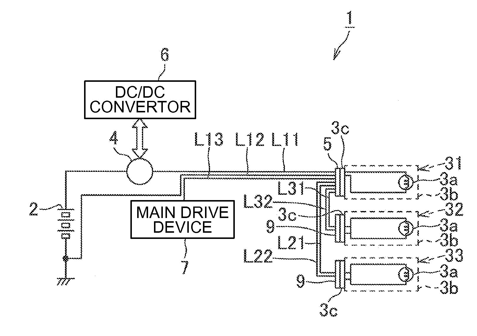
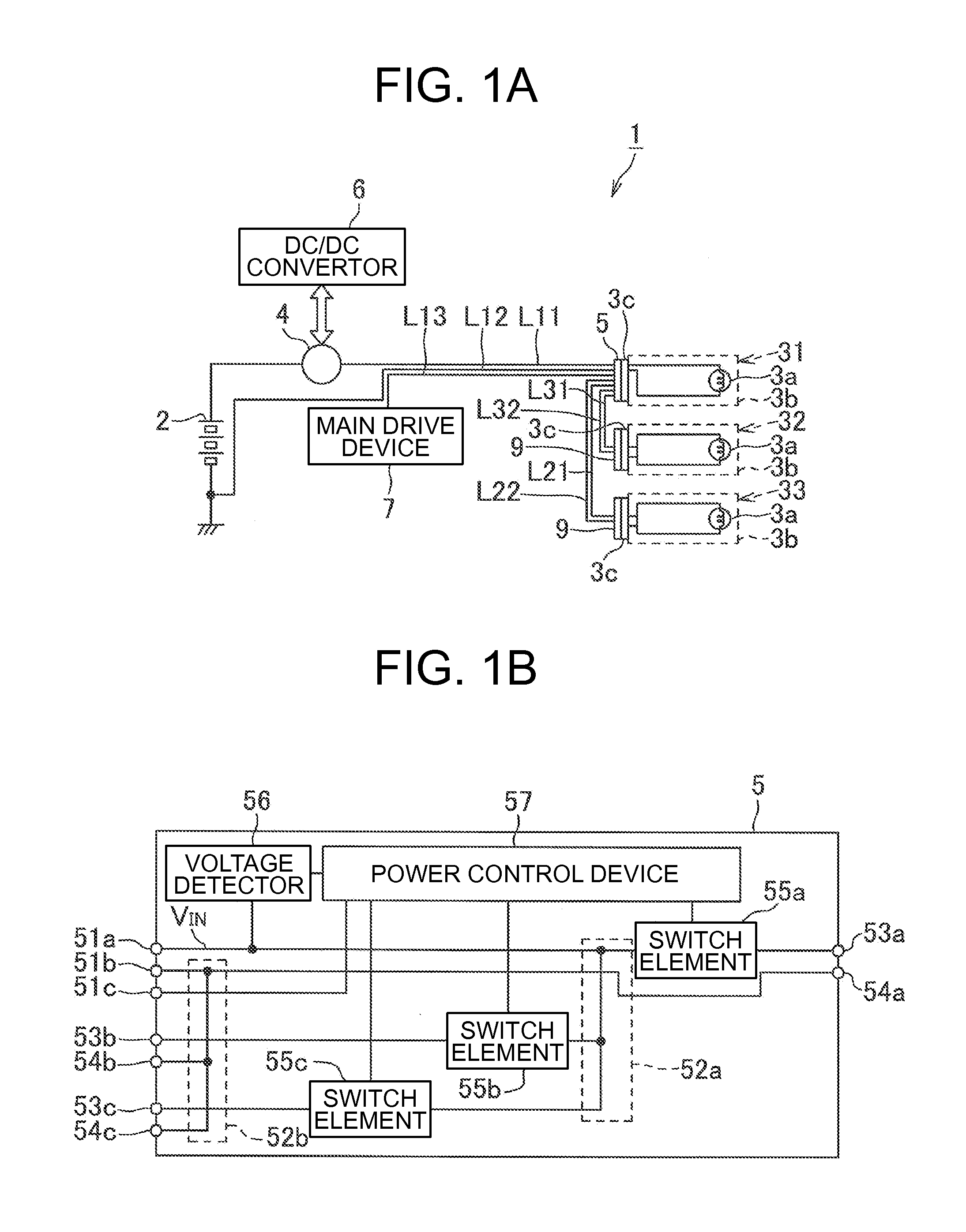
[0040]Hereinafter, with reference to drawings a power supply unit of the present invention is discussed. This power supply unit 1 is the one that is mounted to an ICEC (Internal Combustion Engine Vehicle). As shown in FIG. 1, the power supply unit 1 is provided with a battery 2 as a power source, a plurality of loads 31 to 33 receiving power supply from such the battery 2 to operate, an alternator 4 disposed between the battery 2 and the plurality of loads 31 to 33, a connector 5 connecting a power line L11 connected to the battery 2, ground line L12, and the plurality of loads 31 to 33.

[0041]The aforementioned battery 2 uses what is called a secondary battery such as a lead battery or lithium battery, and is arranged within, e.g., an engine room in the vehicle. The plurality of loads units 31 to 33 is each provided with a ramp load 3a, a holder 3b holding and housing the ramp load 3a, and a connector 3c disposed integral with the holder 3b. These load units 31 to 33 are arranged ne...

second embodiment

[0072]Note that while in the aforementioned first embodiment attaching the connector 5 to the holder 3b of the load unit 31 makes the connector 5 arranged adjacent to the plurality of ramp loads 3a, the invention is not limited to this configuration, the aforementioned connector 5 may be arranged nearer to the plurality of ramp loads 3a than the middle between the battery 2 and the plurality of ramp loads 3a, for example, as shown in FIG. 6, the connector 5 and the load unit 31 may be connected with the power source line L41 and the ground line L41 as cables, so as to connect all the load units 31 and the connector 5 with cables. Also, in this case, the power source terminal 53a and the ground terminal 54b are provided with not only a tub-like shape, but a pressure-bonding blade, and the power source line L41 and the ground line L41 are pressure-bonded.

third embodiment

[0073]Also, when each of the load units 31 to 33 are, for example, arranged as shown in FIG. 7, the connector 5 is arranged in the middle of the load units 31 to 33 as shown in FIG. 7, the connector 5 may be arranged within a range of the power lines L21, L31, L41, and the ground lines L22, L32, L42 being possibly wired, where total cable length of the plurality of power source lines L21, L31, L41, and the ground lines L22, L32, L42 becomes the shortest.


PUM


Abstract

Disclosed is a power supply unit reducing deterioration of power loss caused by cables. A connector connecting a power line L11 connected to a battery and a plurality of ramp loads is attached to a holder housing at least one of the plurality of ramp loads. The connector is provided with: a pressure-bonding power source terminal to which the power line L11 is connected and power is inputted, a first branch circuit branching one power line inputted from the pressure-bonding terminal into a plurality of branch lines, a plurality of tub-like power source terminal, pressure-bonding power terminals each connected to the plurality of branch lines branched by the first branch circuit and outputting power to each ramp load; and a housing them.

Description

TECHNICAL FIELD[0001]This invention relates to power supply units, particularly to power supply units including batteries and a plurality of loads receiving power from the batteries.BACKGROUND ART[0002]Such a vehicle as an automobile has a power supply unit mounted therein for supplying power to a plurality of loads. Well known as this power supply unit is, for example, what is illustrated in FIG. 14. As shown in the figure, the power supply unit 100 is provided with a battery 101, ramp loads 102 as a plurality of loads, and a controller 103 disposed between the battery 101 and the plurality of ramps 102.[0003]The aforementioned controller 103 is mounted to, for example, a power supply box disposed near the battery 101. This controller 103 incorporates a branch circuit 103a branching a power line form the battery 101 into a plurality of branch lines, and a plurality of switch elements 103b each disposed on the branch lines branched by the branch circuit 103a. A Mechanical relay or t...

Claims


Application Information

Patent Timeline
Patent Type & Authority Applications(United States)
IPC IPC(8): B60R16/033H02J1/00
CPCH02J7/14B60Q1/0094B60R16/033H02J2310/46
Inventor SATAKE, SHUUJIKANAZAWA, AKIYOSHI
Owner YAZAKI CORP
Why Eureka
Try Eureka