System and method for incremental forming

Active Publication Date: 2014-06-05
PENN STATE RES FOUND +1
View PDF12 Cites 6 Cited by
  • Summary
  • Abstract
  • Description
  • Claims
  • Application Information

AI Technical Summary

Benefits of technology

This patent describes a new method of sheet metal forming called double-sided incremental forming (DSIF). This method uses two tools to deform and support the metal, resulting in cost savings and better flexibility compared to conventional methods. The system is controlled using software and can accurately position the tools with high accuracy. The technical effects of DSIF include reduced costs, improved forming at lower forces, better control and utilization of non-specific tools, greater mobility of the forming equipment, and improved user-friendliness of the process.

Problems solved by technology

Currently, low volume production of sheet metal components is a relatively high cost, inflexible process, requiring costly sets of dies, typically made of cast steel.
These dies, while well suited to mass production, are poorly matched to relatively low volume production and prototyping needs.
Die sets can cost over $1 million per set, can be difficult to move, and / or costly to modify if the final required geometry of parts is not met.
However, complications still exist in the form of unwanted sheet bending and deformation.
This has been partially addressed with partial and full dies implemented on the opposing side of the forming tool to create a support structure; however, use of such partial or full dies re-introduces the high costs and low flexibility of a die.

Method used


Image

  • System and method for incremental forming
  • System and method for incremental forming
  • System and method for incremental forming

Examples


Embodiment Construction

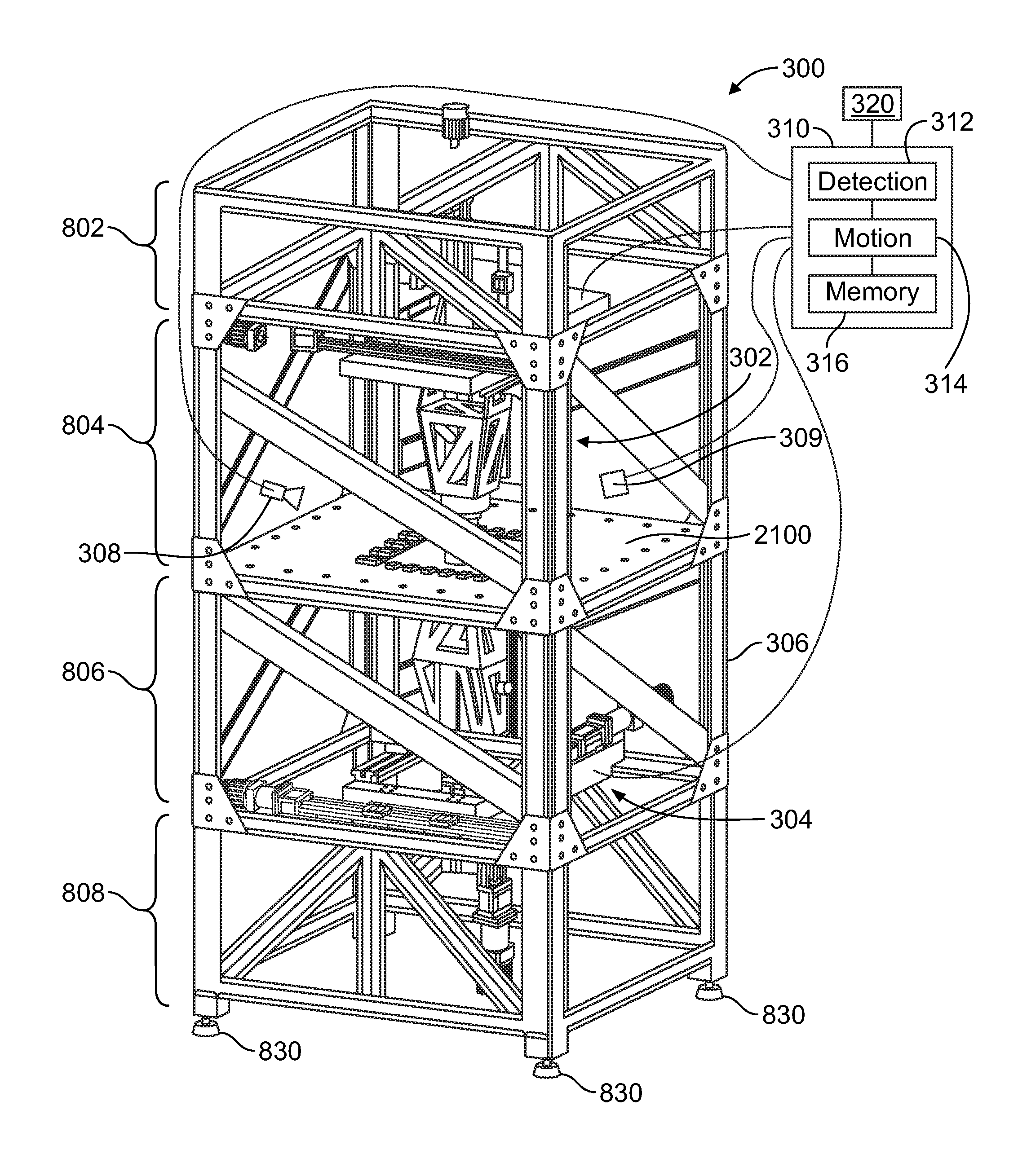
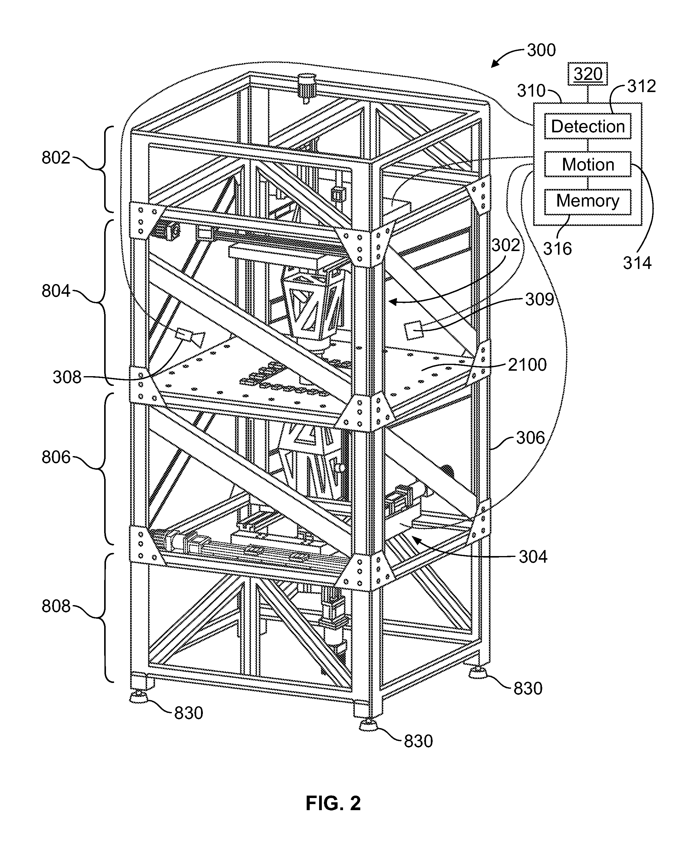
[0029]FIG. 2 is a perspective view of one embodiment of an incremental forming system 300. FIG. 3 is an exploded perspective view of one embodiment of a gantry-style axis assembly 400 of the system 300 in accordance with one embodiment. FIGS. 4 is a perspective view of the axis assembly 400 shown in FIG. 3. As seen in FIG. 2, the system 300 can include a top axis assembly 302 that includes an axis assembly 400 and a bottom axis assembly 304 that includes another axis assembly 400.

[0030]In the embodiment depicted in FIG. 2, the system 300 includes a top tool positioning assembly 302, a bottom tool positioning assembly 304, a frame 306, a thermal imaging camera 308, a heat treatment module 309, and a control module 310, and a blankholder frame 2100. The top tool positioning assembly 302 and the bottom tool positioning assembly 304 are configured to secure forming tools on opposing sides of a workpiece held in the blankholder frame 2100, for example, during a double-sided incremental f...


PUM

PropertyMeasurementUnit
Temperatureaaaaaaaaaa
Currentaaaaaaaaaa
Distributionaaaaaaaaaa

Abstract

A system includes a frame configured to hold a workpiece and first and second tool positioning assemblies configured to be opposed to each other on opposite sides of the workpiece. The first and second tool positioning assemblies each include a toolholder configured to secure a tool to the tool positioning assembly, a first axis assembly, a second axis assembly, and a third axis assembly. The first, second, and third axis assemblies are each configured to articulate the toolholder along a respective axis. Each axis assembly includes first and second guides extending generally parallel to the corresponding axis and disposed on opposing sides of the toolholder with respect to the corresponding axis. Each axis assembly includes first and second carriages articulable along the first and second guides of the axis assembly, respectively, in the direction of the corresponding axis.

Description

CROSS-REFERENCE TO RELATED APPLICATIONS[0001]This application claims priority to U.S. Provisional Application No. 61 / 555,951, which was filed on 4 Nov. 2011, and is entitled “System And Method For Incremental Forming” (the “'951 Application”); U.S. Provisional Application No. 61 / 612,034, which was filed on 16 Mar. 2012, and is entitled “System And Method For Accumulative Double-sided Incremental Forming” (the “'034 Application”); and U.S. Provisional Application No. 61 / 642,598, which was filed on 4 May 2012, and is entitled “System And Method For Accumulative Double-sided Incremental Forming” (the “'598 Application”).[0002]This application also is related to U.S. Nonprovisional application Ser. No. 13 / 654,071, which was filed on 17 Oct. 2012, and is entitled “System And Method For Accumulative Double-sided Incremental Forming” (referred to herein as the “'071 Application”) and U.S. Provisional Application Ser. No. 61 / 550,666, which was filed on 24 Oct. 2011, and is entitled “System ...

Claims


Application Information

Patent Timeline
IPC IPC(8): B21D31/00
CPCB21D31/005B21D37/16
Inventor BELTRAN, MICHAELCAO, JIANROTH, JOHN T.
Owner PENN STATE RES FOUND
Why Eureka
Try Eureka