Density function centric signal processing
- Summary
- Abstract
- Description
- Claims
- Application Information
AI Technical Summary
Benefits of technology
Problems solved by technology
Method used
Image
Examples
first embodiment
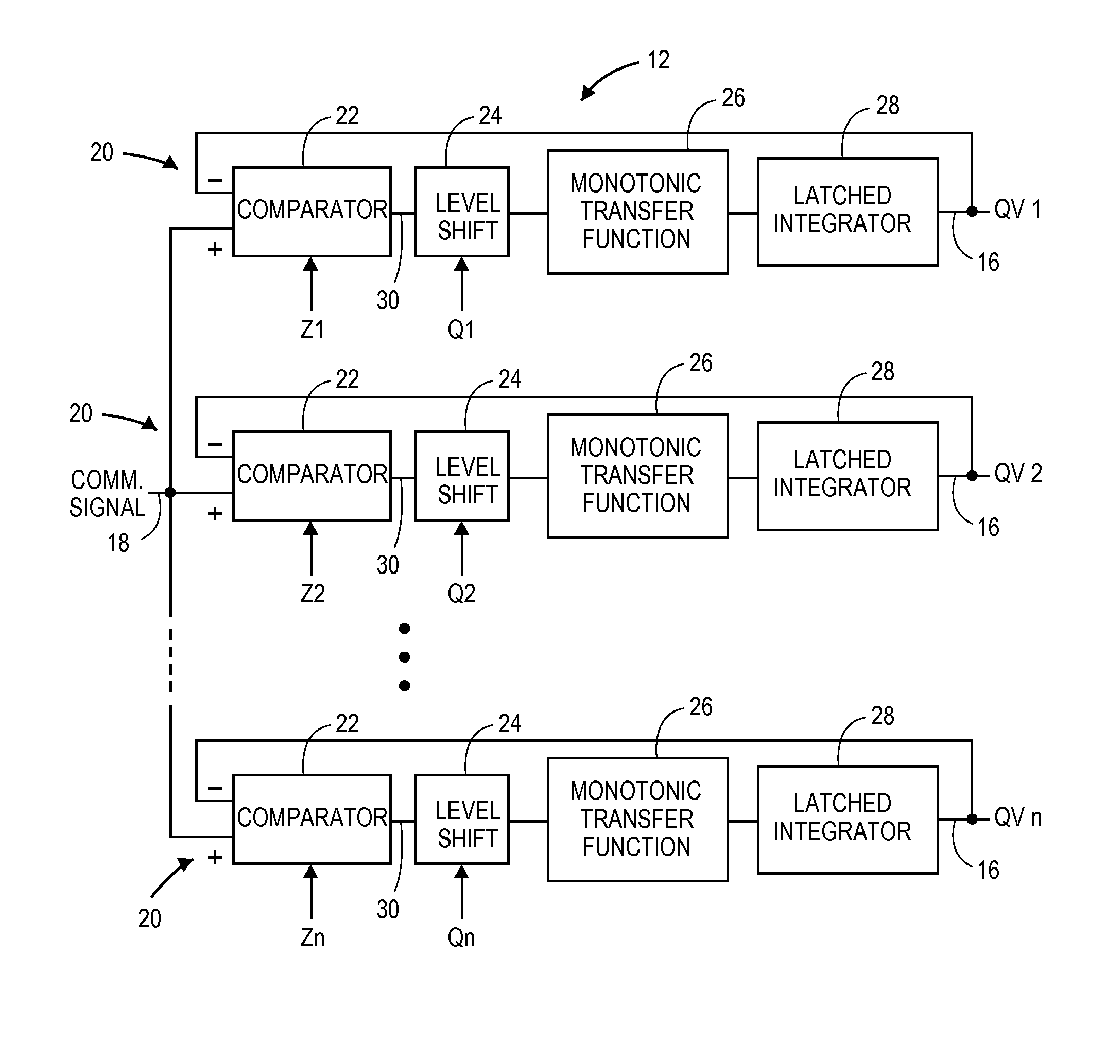
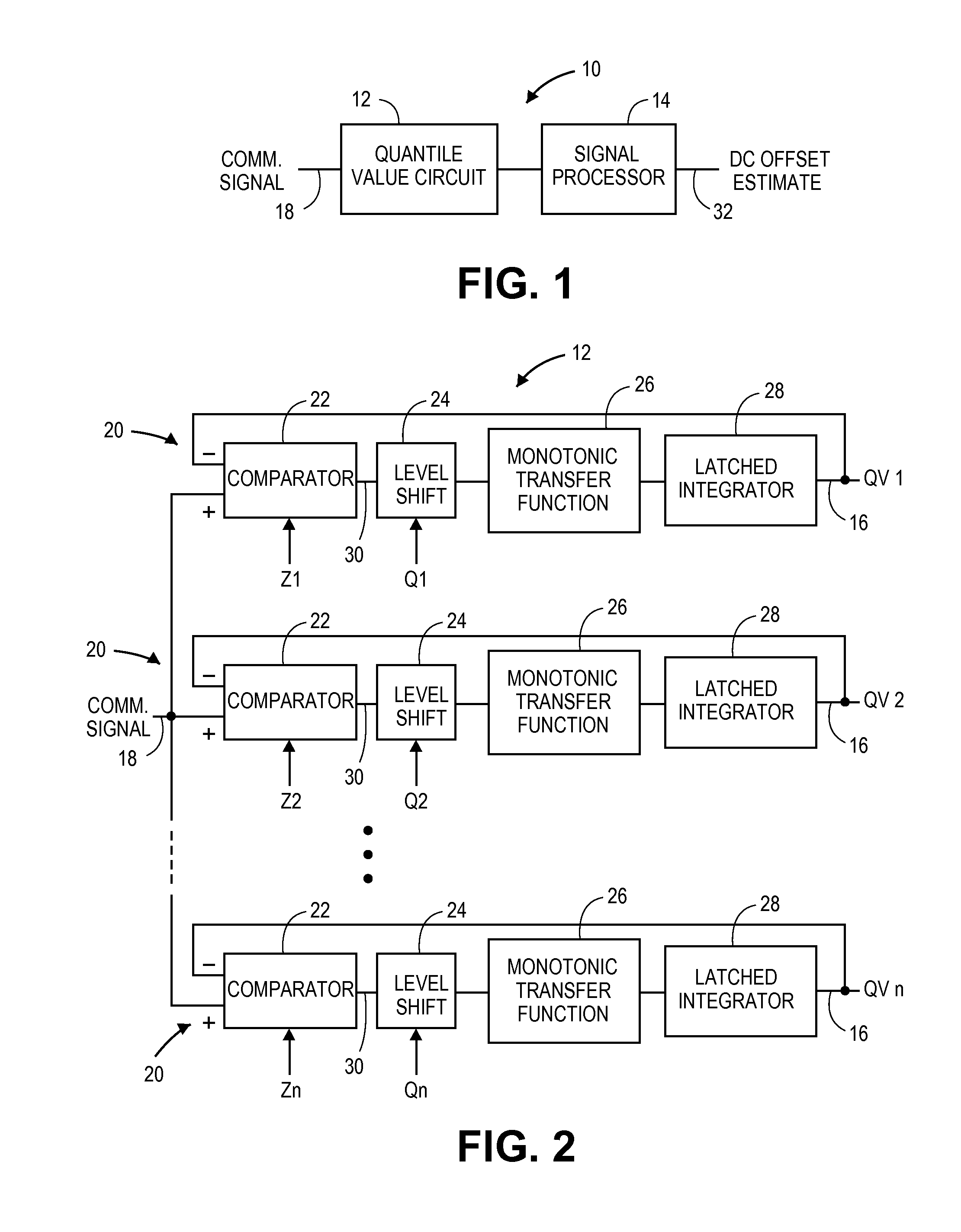
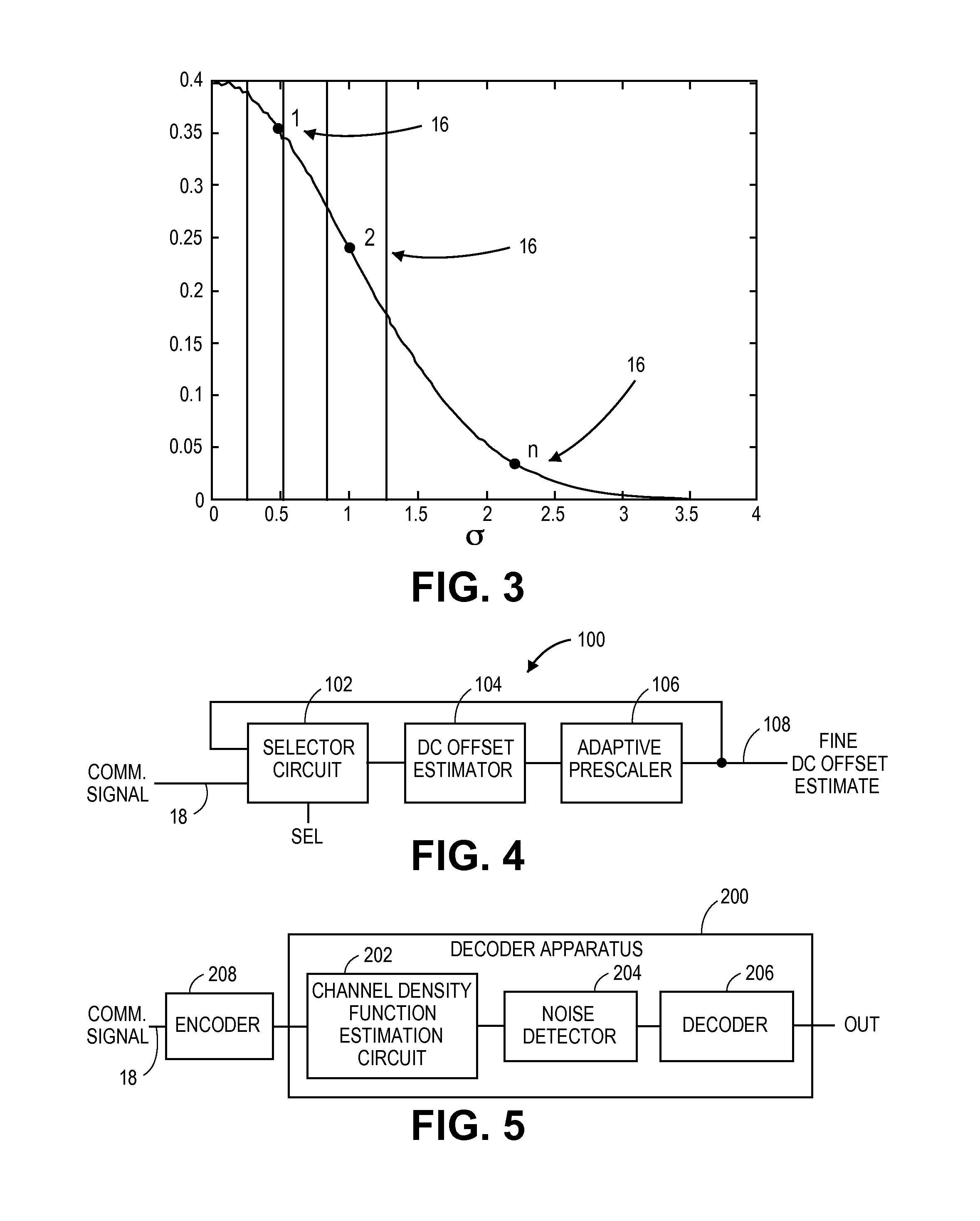
[0033]A circuit 10 for direct current (DC) offset estimation, constructed in accordance with the current invention, is shown in FIG. 1, and may broadly comprise a quantile value circuit 12 and a signal processor 14. The circuit 10 may be utilized in a device that is part of a wired or wireless communications system, such as telephone, internet, and television services in a residence or business, satellite communications, cellular communications, wireless network communications, and the like. The device may be a component such as a cable or digital subscriber line (DSL) modem, a router, a handset, or the like that is subjected to noise or interference from any of a variety of sources. The device may also be a component of a sensor system, such as a voltage meter, a current meter, or a power meter. The circuit 10 may be specifically utilized with a receiver of the device that receives a communications signal. The signal typically is periodic and sinusoidal or square-wave in nature wit...
second embodiment
[0040]A circuit 100 for fine DC offset estimation, constructed in accordance with the current invention, is shown in FIG. 4, and may broadly comprise a selector circuit 102, a DC offset estimator 104, and an adaptive prescaler 106. The circuit 100 may receive the communications signal 18 and may output a fine DC offset estimate 108. The circuit 100 may be utilized in the same fashion as the circuit 10 and may perform a similar function, except that the fine DC offset estimate 108 may provide a higher resolution than the DC offset estimate 32.
[0041]The selector circuit 102 generally selects one of two or more signals to pass through to its output. The selector circuit 102 may receive the communications signal 18 at a first input and the fine DC offset estimate 108 at a second input. The selector circuit 102 may output either the communications signal 18 or the fine DC offset estimate 108 depending on the state of a select line 110, which may have a binary value to select either the f...
third embodiment
[0044]A decoder apparatus 200, constructed in accordance with the current invention, is shown in FIG. 5, and may broadly comprise a channel density function estimation circuit 202, a noise detector 204, and a decoder 206. The decoder apparatus 200 may be utilized in a communication system when receiving a signal on a channel that has already been encoded by an encoder 208 with a symbol-based encoding or modulation scheme, such as frequency or phase shift keying, quadrature amplitude modulation, or the like. The system may also utilize forward error correction schemes, such as turbo codes or low-density parity-check codes, which take probabilities as inputs rather than bits. Thus, instead of zeros and ones, the input is the likelihood each bit is a zero or a one. A decoder typically uses iterative hypothesis testing to arrive at the original message. Bit likelihoods are derived from symbol likelihoods, which are typically determined by the Euclidian distance a symbol is from the clos...
PUM
 Abstract
Description
Claims
Application Information
 - R&D
- Intellectual Property
- Life Sciences
- Materials
- Tech Scout
- Unparalleled Data Quality
- Higher Quality Content
- 60% Fewer Hallucinations
Browse by: Latest US Patents, China's latest patents, Technical Efficacy Thesaurus, Application Domain, Technology Topic, Popular Technical Reports.
© 2025 PatSnap. All rights reserved.Legal|Privacy policy|Modern Slavery Act Transparency Statement|Sitemap|About US| Contact US: help@patsnap.com


