
Method for distributed waveform recording in a power distribution system

a technology of power distribution system and waveform recording, applied in the field of power distribution system, can solve the problems of low resolution waveform recording, inability to perform waveform recording in a desired manner, and inability to achieve the desired effect of waveform recording,

Active Publication Date: 2014-05-15
ABB (SCHWEIZ) AG
View PDF1 Cites 31 Cited by
  • Summary
  • Abstract
  • Description
  • Claims
  • Application Information

AI Technical Summary

Benefits of technology

This patent describes a method and apparatus for recording waveform data in a power distribution system. The system includes multiple devices that communicate with each other in various levels of the system. When an event is detected, the system can trigger waveform recording to capture data from the affected devices. The captured data is then used to create a visual representation of the event. The technical effect of this invention is to improve the accuracy and responsiveness of detecting and troubleshooting power distribution system issues.

Problems solved by technology

The current power distribution systems, however, are not able to perform waveform recording in a desired manner due to various limitations.
Due to memory limitations, duration of the pre-fault and post-fault records in the waveform may get restricted.
Besides that, the protection devices most often operate at lower sampling rates leading to a low resolution waveform recording.
This condition can cause limitations in root cause analysis and create dependencies on the dedicated waveform recorder IED which is comparatively a costly solution.
In some known power distribution systems, the waveform recording function present in protection IEDs can sample from 4 to 128 samples / cycle, the sampling rate can be limited because of input filters providing filtered quantities for main protection and control functions.
Thus, the recording device may have limitations on its sampling capabilities.
Thus, the fault waveforms recorded by these substation automation devices in a distributed manner may result in timing inaccuracies.
This configuration can result in deviations in the timing information of disturbance data recorder in distributed devices.
With a Merging Unit present in the process bus, the usage of dedicated DFRs can be expensive and also reduce the availability of the overall system as it contributes to an increase in the number of automation elements resulting in reduced Mean Time Between Failure (MTBF).

Method used


Image

  • Method for distributed waveform recording in a power distribution system
  • Method for distributed waveform recording in a power distribution system
  • Method for distributed waveform recording in a power distribution system

Examples


example

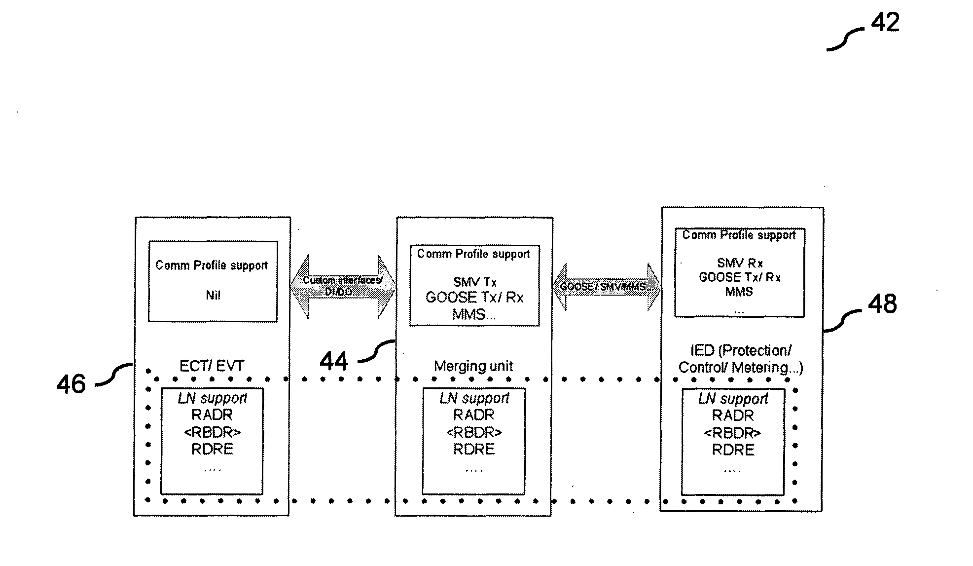
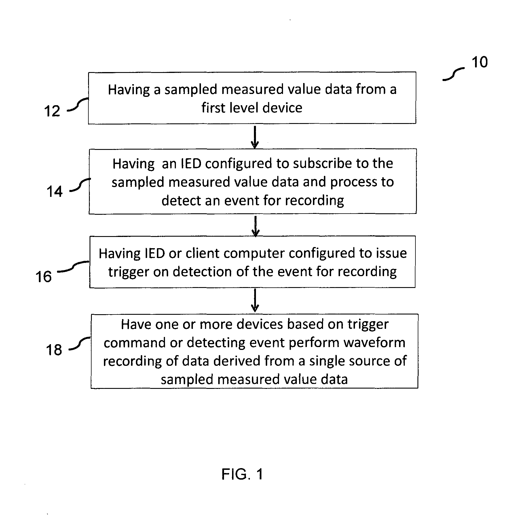
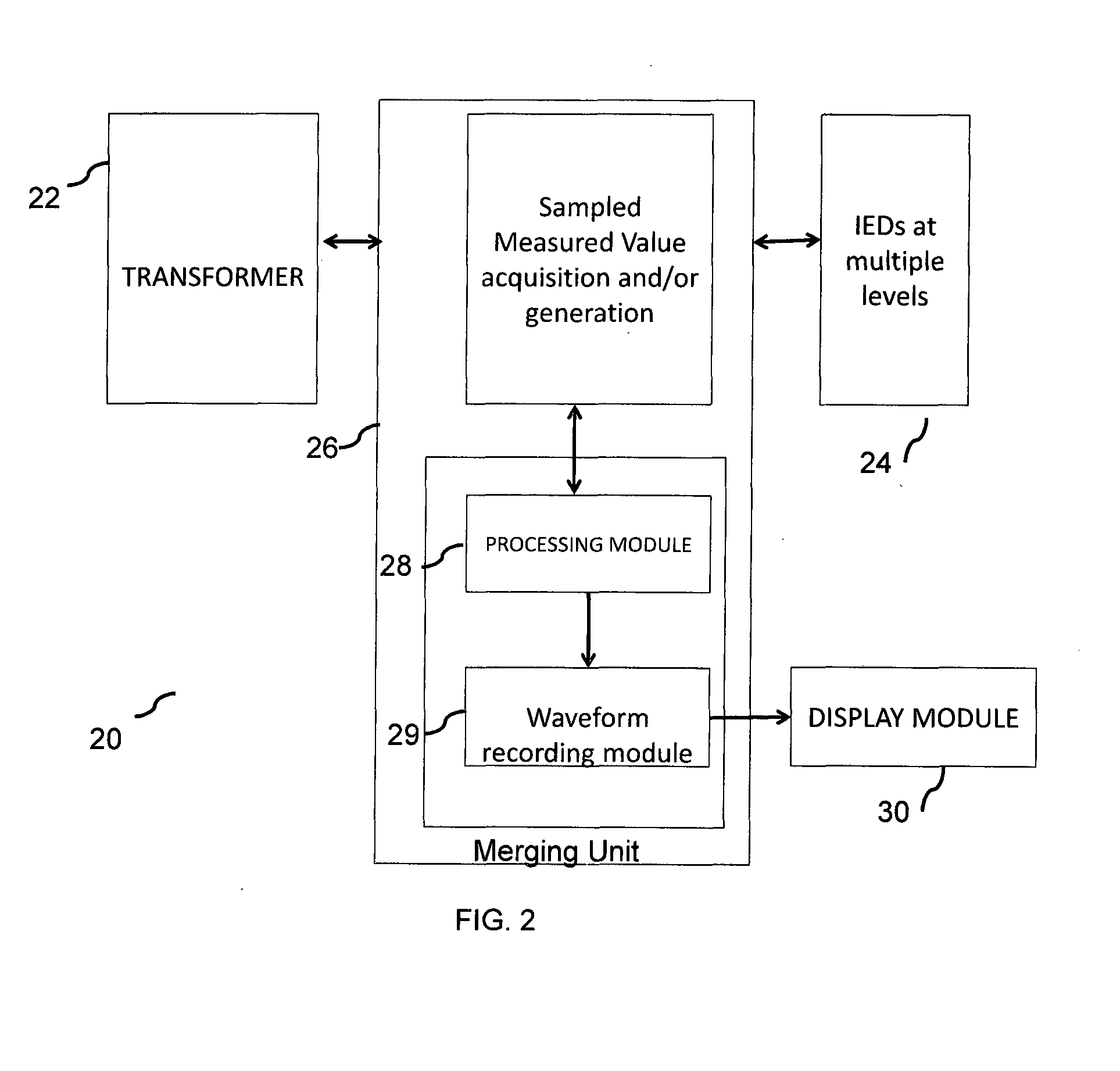
[0053]In one example according to the exemplary embodiments disclosed herein, the power distribution system architecture for effective fault analysis is based on implementing the waveform recording feature in Merging Unit and IEDs (protection, etc.,) in various levels of the power distribution system automation hierarchy using the same stream of raw data.

[0054]The Merging unit can provide a digital interface for the instrument transformers acquire sampled measured value data from the instrument transformers at a high sampling rate, and publish the sampled measured value data to the process bus network at the same and / or reduced sampling rate based on methods such as interpolation. In this arrangement, it can be advantageous to record the waveform at different levels using different devices such as can be merging unit, protection and control IEDs, DFRs, or other suitable devices based on the incoming sampling rates to these IEDs, which are in turn based on a single stream of sampled ...


PUM


Abstract

An exemplary method and apparatus are directed to distributed waveform recording for fault monitoring and analysis of a fault condition in a power distribution system. One or more instrument transformers along with merging units and a plurality of Intelligent Electronic Devices (IEDs) distributed in a plurality of hierarchical levels. The distributed waveform recording corresponds to a fault event at different levels in the power distribution system data is carried out by at least two devices configured to detect an event for recording and perform waveform recording. The data used for waveform recording and the data for detection of the event are based on a single stream of the sampled measured value data and are thereby are time synchronized.

Description

RELATED APPLICATION[0001]This application claims priority under 35 U.S.C. 120 to International application PCT / IB2012 / 001301 filed on Jun. 29 2012, designating the U.S., and claiming priority to Indian application 2232 / CHE / 2011 filed in India on Jun. 30 2011. The content of each prior application is hereby incorporated by reference in its entirety.FIELD[0002]The present disclosure relates to a power distribution system and particularly to a method and apparatus of distributed waveform recording for fault monitoring and analysis of fault condition.BACKGROUND INFORMATION[0003]An electrical or power substation includes electricity transmission and distribution systems where high and low voltages are stepped down or up, respectively using transformers. Electric power may flow through several substations between generating plant and consumer or load, and may be transformed in voltage in several steps.[0004]Known substations can include a plurality of power and distribution transformers, ...

Claims


Application Information

Patent Timeline
IPC IPC(8): G05B15/02
CPCG05B15/02H02H7/26H04Q9/00H04Q2209/20H04Q2209/60
Inventor GOPALAKRISHNAN, VIVEKKUMAR S.R., SASIDECK, BERNHARD
Owner ABB (SCHWEIZ) AG
Learn More