
Method and apparatus for wirelessly receiving power

a wireless receiving and wireless technology, applied in the direction of exchanging data chargers, batteries, data exchange, etc., can solve the problems of waste of resources, loss of efficiency, and mismatch of the maximum power supported by the transmitting and receiving devices

Active Publication Date: 2014-05-08
O2 MICRO INT LTD
View PDF5 Cites 21 Cited by
  • Summary
  • Abstract
  • Description
  • Claims
  • Application Information

AI Technical Summary

Benefits of technology

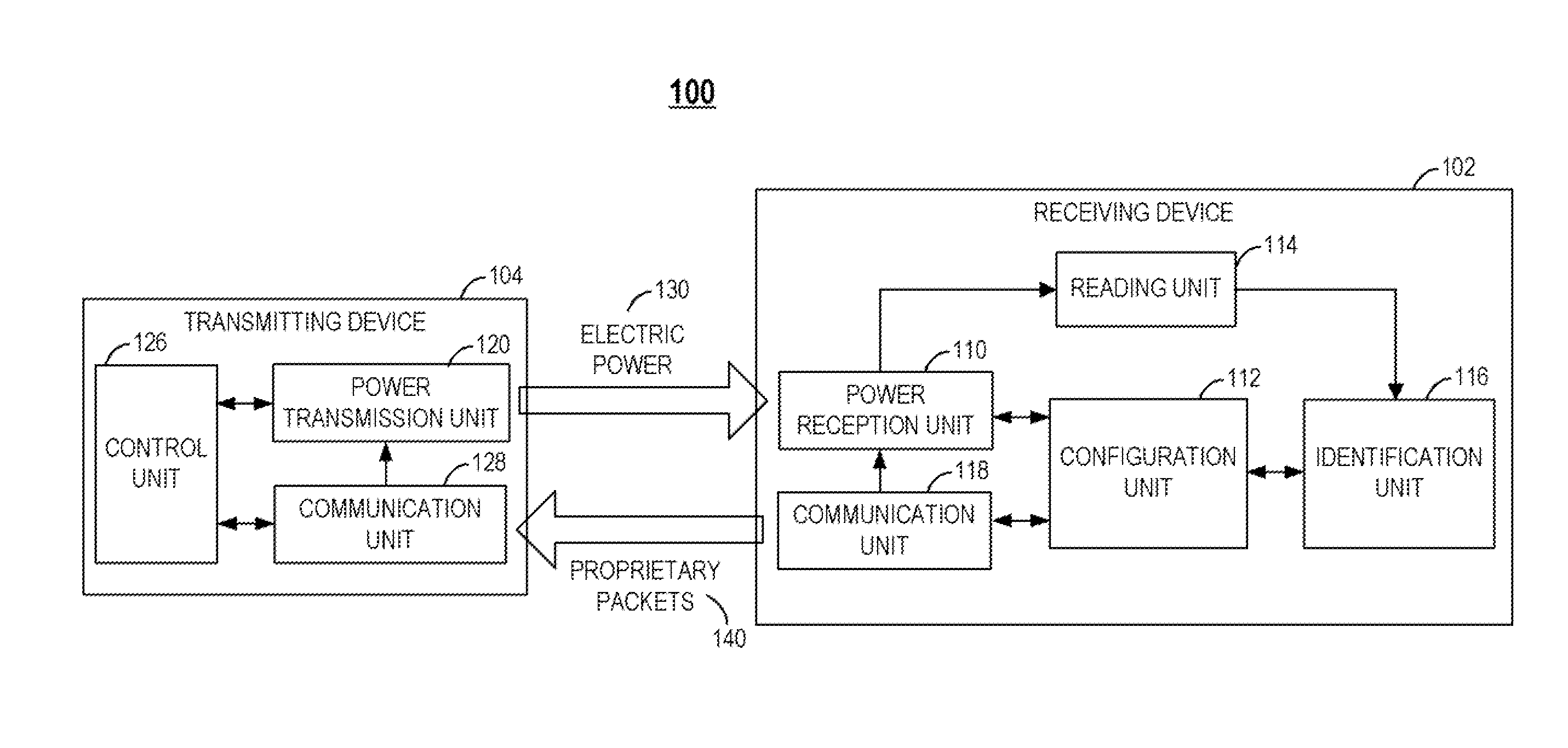
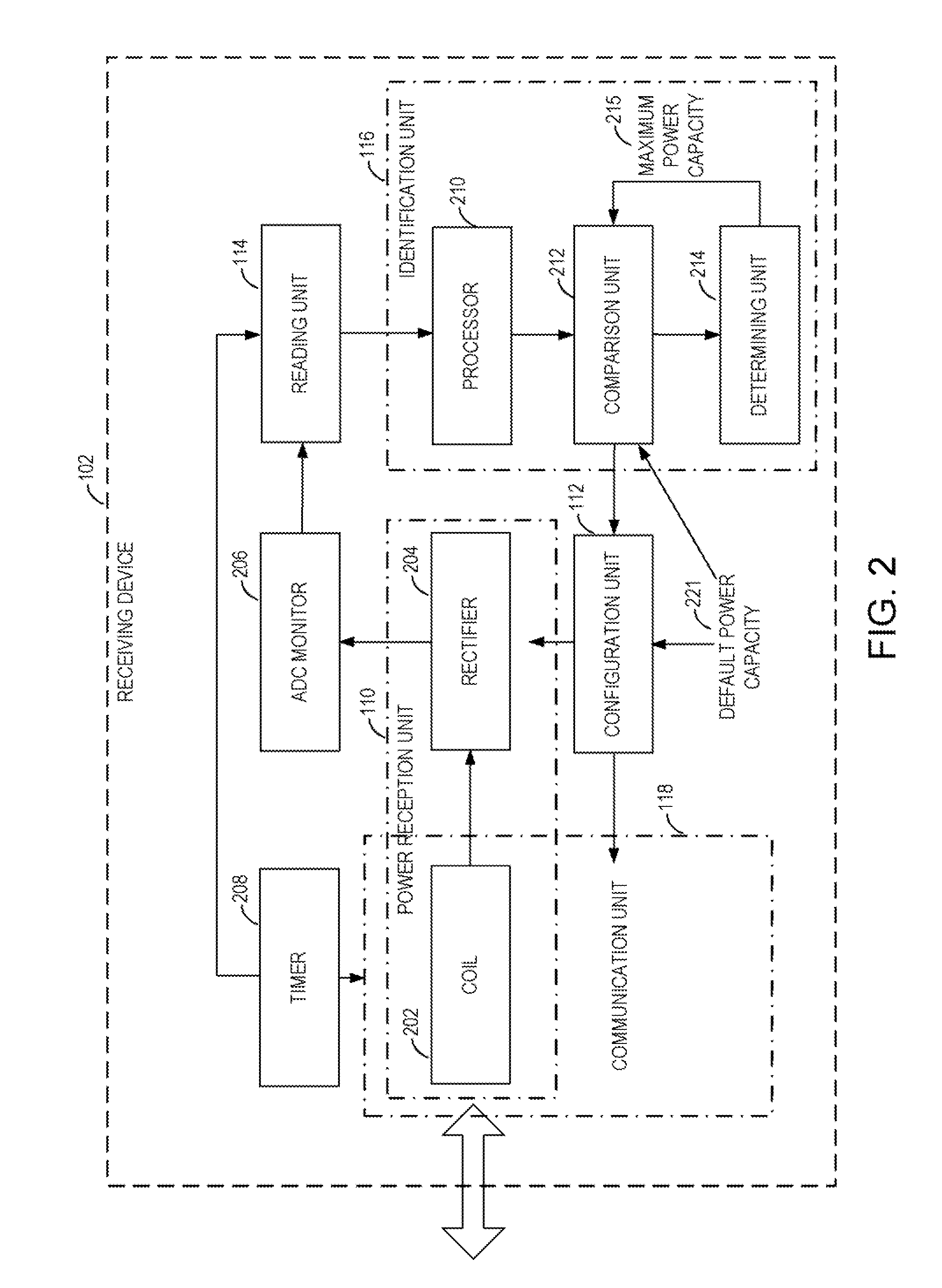
The patent is for a method for a receiving device to wirelessly receive electric power from a transmitting device. The method involves setting a default power capacity for the transmitting device based on information known by both the receiving device and the transmitting device. The electric power is then transmitted to the receiving device. The receiving device reads certain values associated with the electric power and identifies the maximum power capacity of the transmitting device based on those values and a predetermined threshold. This threshold can be adjusted based on certain parameters controlled by the transmitting device. The technical effect of this patent is to enable efficient transfer of electric power between devices and to optimize the use of available power capacity.

Problems solved by technology

However, as some transmitting devices and receiving devices can support higher output power than 5 W, there may be a mismatch of the maximum power supported by the transmitting and receiving devices in the wireless power transmission system.
Moreover, if both the transmitting and receiving devices operate with 5 W maximum, regardless of their maximum power supports, there may be a waste of resource or a loss of efficiency since both the transmitting and receiving devices may support a higher power, e.g., 10 W.

Method used


Image

  • Method and apparatus for wirelessly receiving power
  • Method and apparatus for wirelessly receiving power
  • Method and apparatus for wirelessly receiving power

Examples


Embodiment Construction

[0025]Reference will now be made in detail to the embodiments of the present disclosure, examples of which are illustrated in the accompanying drawings. While the present disclosure will be described in conjunction with the embodiments, it will be understood that they are not intended to limit the present disclosure to these embodiments. On the contrary, the present disclosure is intended to cover alternatives, modifications, and equivalents, which may be included within the spirit and scope of the present disclosure as defined by the appended claims.

[0026]Furthermore, in the following detailed description of embodiments of the present disclosure, numerous specific details are set forth in order to provide a thorough understanding of the present disclosure. However, it will be recognized by one of ordinary skill in the art that the present disclosure may be practiced without these specific details. In other instances, well-known methods, procedures, components, and circuits have not...


PUM


Abstract

Method and apparatus for a receiving device to wirelessly receive electric power from a transmitting device. A power capacity is configured at the receiving device, based on a default power capacity known by both the receiving device and the transmitting device. A first value of a dependent parameter is read. The dependent parameter is associated with the electric power and varies in accordance with an independent parameter adjustable by the transmitting device. A second value of the dependent parameter is then read. A maximum power capacity of the transmitting device is identified based on at least the first and second values and a predetermined threshold. The electric power is then received from the transmitting device.

Description

BACKGROUND[0001]1. Technical Field[0002]The disclosure relates generally to a method and apparatus for wirelessly receiving power.[0003]2. Discussion of Technical Background[0004]Wireless power transmission is the transmission of electrical energy from a power source to an electrical load without interconnecting manmade conductors. The most common form of wireless power transmission is carried out using direct induction followed by resonant magnetic induction. Other methods include electromagnetic radiation in the form of microwaves or lasers and electrical conduction. Wireless power transmission has been used for battery charging, or other suitable loads, in a wide range of mobile devices, such as mobile phone, camera, music player, headset, etc.[0005]In a wireless power transmission system, the receiving device (receiver) may provide control information to the transmitting device (transmitter) by, for example, load modulation on the power signal. Based on the received control info...

Claims


Application Information

Patent Timeline
Patent Type & Authority Applications(United States)
IPC IPC(8): H02J17/00
CPCH02J50/80H02J7/00034H02J50/12H04B5/72H04B5/79
Inventor CHEN, JUNWANG, QIANGYU, MEIPENG, XINSHENGWANG, JAMES
Owner O2 MICRO INT LTD
Learn More