Axial Flow Turbine

a flow turbine and axial flow technology, applied in the direction of machines/engines, stators, liquid fuel engines, etc., can solve the problems of increasing friction loss, insufficient etc., to reduce the circumferential velocity component, and enhance the effect of reducing mixing loss

Active Publication Date: 2014-05-01
MITSUBISHI POWER LTD
View PDF8 Cites 26 Cited by
  • Summary
  • Abstract
  • Description
  • Claims
  • Application Information

AI Technical Summary

Benefits of technology

[0018]In the aspect of the present invention described above, a portion of working fluid (leaking fluid) flows into the clearance passage from the downstream side of the stator blade (the upstream side of the rotor blade in the main passage) and flows out toward the downstream side of the rotor blade in the main passage via the clearance passage. In this case, the leaking fluid that has flowed into the clearance passage from the downstream side of the stator blade in the main passage forms a flow having a large circumferential velocity component. However, a portion of the leaking fluid flows into the circulation flow generating chamber and hits the shielding plates, which can generate a circulation flow having a suppressed circumferential velocity component. The interference of the circulation flow thus generated can effectively reduce the circumferential velocity component of the flow of the leaking fluid flowing out from the clearance passage toward the downstream side of the rotor blade in the main passage. Thus, the flowing direction of the leaking fluid can coincide with that of the working fluid (the main-flow fluid) that has passed the rotor blade, which enhances the effect of reducing the mixing loss.
[0019]The present invention can enhance the effect of reducing the mixing loss.

Problems solved by technology

Therefore, unless the number of the guide plates is increased to narrow the interval between the guide plates, an effect of changing the flowing direction of the leaking fluid cannot sufficiently be produced, which leads to a possibility that the effect of reducing the mixing loss cannot be sufficiently obtained.
Contrarily, if the number of the guide plates is increased to narrow the interval between the guide plates, increase in a contact area increases a friction loss, which may cancel out the effect of reducing the mixing loss.

Method used


Image

  • Axial Flow Turbine
  • Axial Flow Turbine
  • Axial Flow Turbine

Examples


first embodiment

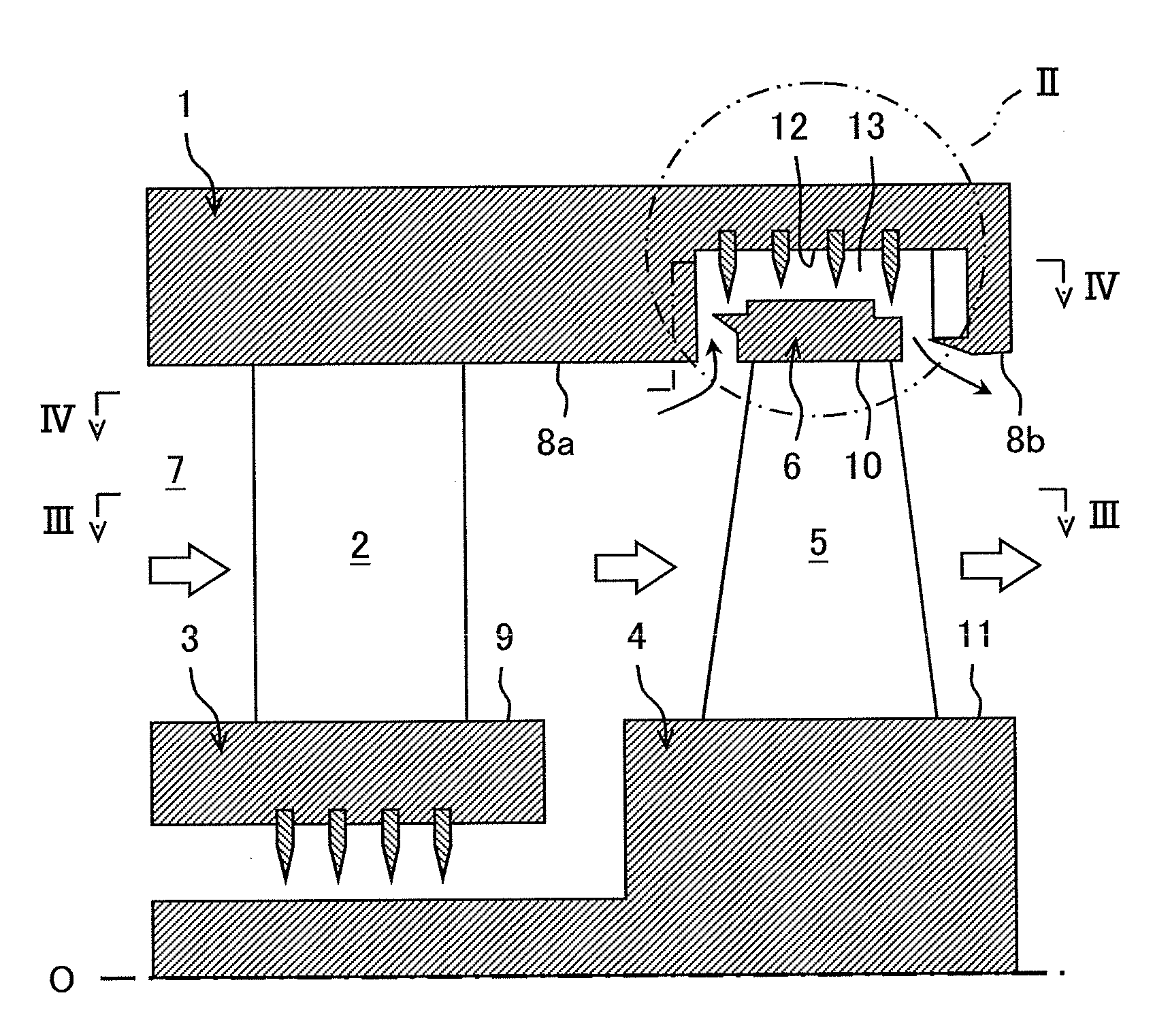
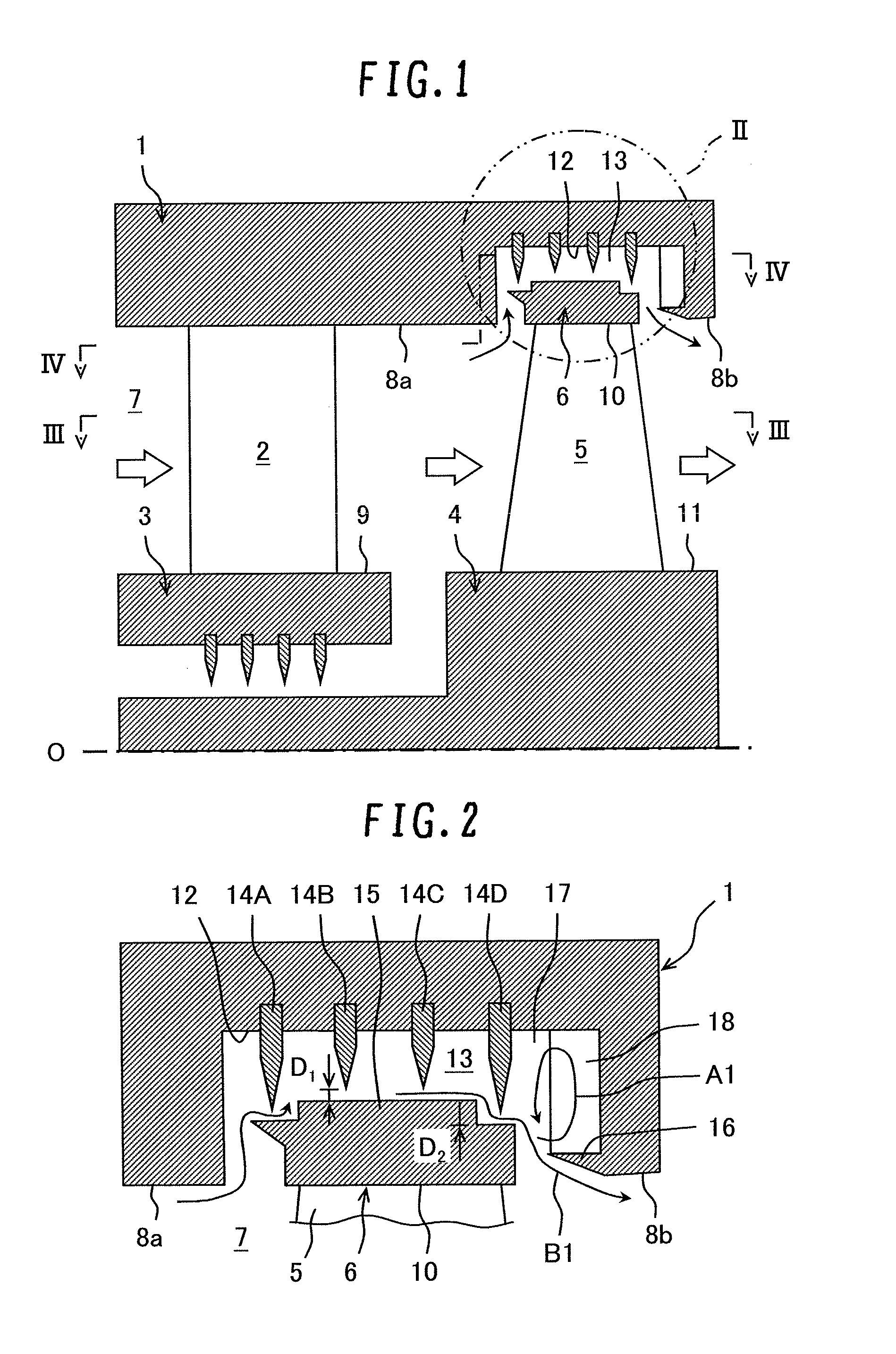
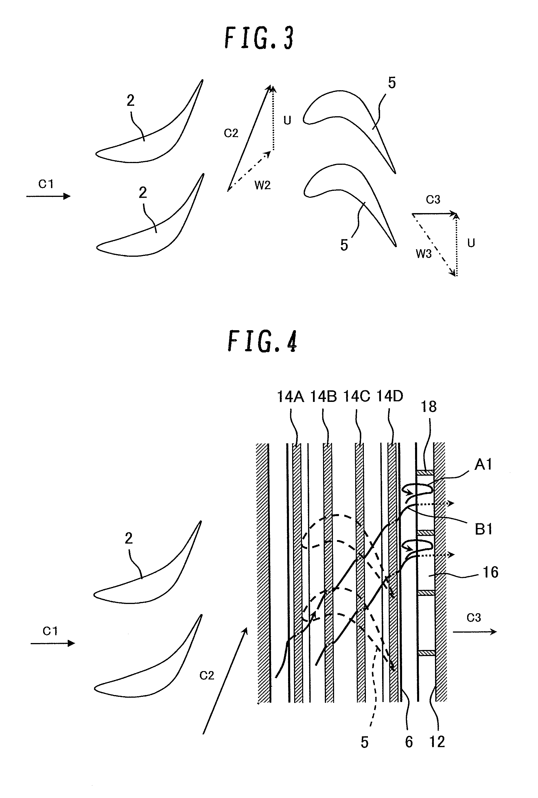
[0030]FIG. 1 is a schematic cross-sectional view of a partial structure (a stage structure) of a steam turbine as viewed in a rotor-axial direction according to the present invention. FIG. 2 is a partial enlarged cross-sectional view of a II-part in FIG. 1, illustrating a detailed structure of a clearance passage. FIG. 3 is a cross-sectional view as viewed in a rotor-circumferential direction taken along line III-III in FIG. 1, illustrating a flow in a main passage. FIG. 4 is a cross-sectional view as viewed in the rotor-circumferential direction taken along line IV-IV, illustrating a flow in the clearance passage together with the flow in the main passage.

[0031]Referring to FIGS. 1 to 4, a steam turbine includes an annular diaphragm outer ring 1 (a stationary body) provided on the inner circumferential side of a casing (not shown), a plurality of stator blades 2 provided on the inner circumferential side of the diaphragm outer ring 1, and an annular diaphragm inner ring 3 provided ...

second embodiment

[0058]the present invention is described with reference to FIG. 9. In the present embodiment the same portions as those in the above first embodiment are denoted by like reference numerals and their explanations are arbitrarily omitted.

[0059]FIG. 9 illustrates a detailed structure of a clearance passage according to the second embodiment.

[0060]In the present embodiment, a cutout is formed in the downstream side end portion of a shroud 6C. Specifically, the shroud 6C has an outer circumferential surface 21a to which a final-stage seal fin 14D is opposed, an outer circumferential surface 21b which is located on the rotor-radial outside (the upside in the figure) of the outer circumferential surface 21a and to which the seal fin 14C anterior to the final stage seal fin is opposed, and a stepped lateral surface 22 formed between the outer circumferential surface 21a and the outer circumferential surface 21b.

[0061]A clearance dimension D1 between the tip of each seal fin and the outer c...


PUM


Abstract

An axial flow turbine that can enhance an effect of reducing a mixing loss is disclosed. The axial flow turbine includes a plurality of stator blades provided on the inner circumferential side of a diaphragm outer ring; a plurality of rotor blades provided on the outer circumferential side of a rotor; a shroud provided on the outer circumferential side of the plurality of rotor blades; an annular groove portion formed in the diaphragm outer ring and housing the shroud therein; a clearance passage defined between the groove portion and the shroud, into which a portion of working fluid flows from the downstream side of the stator blades in a main passage; seal fins provided in the clearance passage; a circulation flow generating chamber defined on the downstream side of the clearance passage; and a plurality of shielding plates secured to the diaphragm outer ring.

Description

BACKGROUND OF THE INVENTION[0001]1. Field of the Invention[0002]The present invention relates to an axial flow turbine used as a steam turbine, a gas turbine or the like for a power-generating plant.[0003]2. Description of the Related Art[0004]An improvement in the power generation efficiency of the power-generating plant has recently led to a strong demand for further improved turbine performance. The turbine performance has a relationship with a stage loss, an exhaust loss, a mechanical loss and the like associated with the turbine, and it is considered most effective to reduce the stage loss among them for further improvement.[0005]The stage loss includes various losses, which are broadly divided into:[0006](1) a profile loss attributable to airfoil per se,[0007](2) a secondary flow loss attributable to a flow not along with a main flow, and[0008](3) a leakage loss caused by working fluid (steam, gas or the like) leaking to outside the main passage.[0009]The above leakage loss in...

Claims


Application Information

Patent Timeline
Patent Type & Authority Applications(United States)
IPC IPC(8): F01D11/08
CPCF01D11/08F01D5/225F02C7/28F01D9/041F05D2220/31F05D2240/11F05D2240/12F05D2240/30
Inventor SHIBATA, TAKANORINISHIJIMA, NORIYOSEGAWA, KIYOSHIFUKUSHIMA, HISATAKALEE, GOINGWON
Owner MITSUBISHI POWER LTD
Why Eureka
Try Eureka