
Methods and apparatus for evaluating downhole conditions with RFID MEMS sensors

a technology of mems sensors and downhole conditions, applied in the field of subterranean well drilling, completion, servicing, etc., can solve the problems of affecting the integration of sealant, affecting the safety of drilling personnel,

Active Publication Date: 2014-04-24
HALLIBURTON ENERGY SERVICES INC
View PDF13 Cites 67 Cited by
  • Summary
  • Abstract
  • Description
  • Claims
  • Application Information

AI Technical Summary

Benefits of technology

The patent text describes a system and method for using RFID tags with MEMS sensors to detect properties of wellbore servicing fluids in real-time. This technology can be used to monitor the health of the sealant used in wellbore servicing operations, by measuring parameters such as moisture content, temperature, pH, and ion concentration. The use of RFID tags allows for the improvement of sealant integrity and the detection of abnormal conditions in the wellbore, formation, wellbore servicing tool, or combinations thereof. This technology can also be used to improve the monitoring and detection of wellbore parameters such as position and location.

Problems solved by technology

The integrity of sealant can be adversely affected by conditions in the well.
For example, cracks in cement may allow water influx while acid conditions may degrade cement.
Active, embeddable sensors can involve drawbacks that make them undesirable for use in a wellbore environment.
For example, low-powered (e.g., nanowatt) electronic moisture sensors are available, but have inherent limitations when embedded within cement.
The highly alkali environment can damage their electronics, and they are sensitive to electromagnetic noise.
Additionally, power must be provided from an internal battery to activate the sensor and transmit data, which increases sensor size and decreases useful life of the sensor.

Method used


Image

  • Methods and apparatus for evaluating downhole conditions with RFID MEMS sensors
  • Methods and apparatus for evaluating downhole conditions with RFID MEMS sensors
  • Methods and apparatus for evaluating downhole conditions with RFID MEMS sensors

Examples


Embodiment Construction

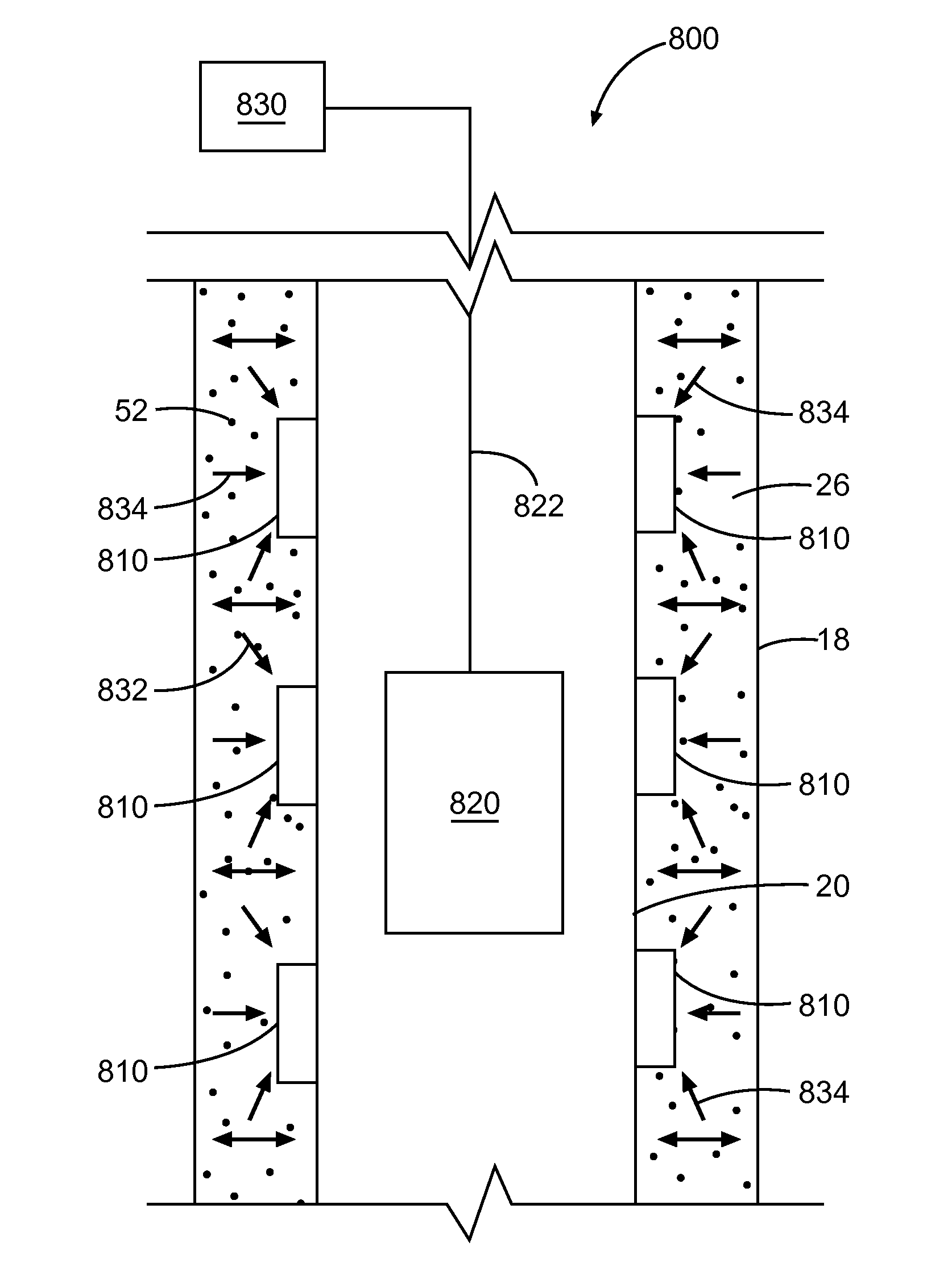
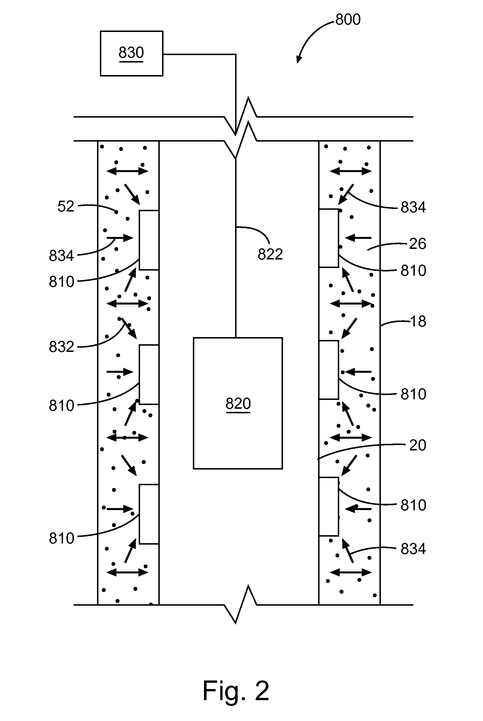
[0019]Disclosed herein are methods for detecting and / or monitoring the position and / or condition of a wellbore, a formation, a wellbore service tool, and / or wellbore compositions, for example wellbore sealants such as cement, using MEMS-based data sensors. Still more particularly, the present disclosure describes methods of monitoring the integrity and performance of wellbore compositions over the life of the well using MEMS-based data sensors. Performance may be indicated by changes, for example, in various parameters, including, but not limited to, moisture content, temperature, pH, and various ion concentrations (e.g., sodium, chloride, and potassium ions) of the cement. In embodiments, the methods comprise the use of embeddable data sensors capable of detecting parameters in a wellbore composition, for example a sealant such as cement. In embodiments, the methods provide for evaluation of sealant during mixing, placement, and / or curing of the sealant within the wellbore. In anot...


PUM


Abstract

A radio frequency identification (RFID) tag can include a die attached to an inductive-capacitive (LC) circuit including a capacitive element coupled to an inductive element. The LC circuit can have a resonant frequency that varies according to properties of fluid proximate the RFID tag. The RFID tag can further include a coating material disposed around the die to form an outer surface of the RFID tag. The coating material may have a thickness over a portion of the LC circuit, to permit a conductivity property of a fluid proximate the outer surface to affect the resonant frequency of the LC circuit such that the resonant frequency shifts to a second resonant frequency. Additional apparatus, systems, and methods are disclosed.

Description

CROSS-REFERENCE TO RELATED APPLICATIONS[0001]This is a continuation-in-part application of U.S. patent application No. 13 / 031,519, filed Feb. 21, 2011, published as U.S. Patent Application Publication 2011 / 0199228; which is a continuation-in-part application of U.S. patent application Ser. No. 12 / 618,067, filed on Nov. 13, 2009, now U.S. Pat. No. 8,342,242, which is a continuation-in-part of U.S. patent application Ser. No. 11 / 695,329, now U.S. Pat. No. 7,712,527, all entitled “Use of Micro-Electro-Mechanical Systems (MEMS) in Well Treatments,” each of which is hereby incorporated by reference herein in its entirety, and for all purposes.BACKGROUND OF THE INVENTION[0002]This disclosure relates to the field of drilling, completing, servicing, and treating a subterranean well such as a hydrocarbon recovery well. In particular, the present disclosure relates to systems and methods for detecting properties of wellbore servicing fluids based on the responses that these properties can gen...

Claims


Application Information

Patent Timeline
IPC IPC(8): E21B47/12G06K19/077
CPCG06K19/07749E21B47/122E21B33/13E21B43/25E21B47/01E21B47/005E21B47/13G06K19/0717G06K19/077E21B47/12
Inventor ROBERSON, MARK W.RODDY, CRAIG W.BARTEE, CHARLESMCGUIRE, KRISTOPHERRAVI, KRISHNA M.ROTHROCK, GINGERGOODWIN, SCOTT
Owner HALLIBURTON ENERGY SERVICES INC
Learn More