
Connecting rod for refrigeration compressors

a technology for connecting rods and compressors, which is applied in the direction of mechanical control devices, instruments, lighting applications, etc., can solve the problems of bearing wear, deformation, and large mechanical loss, and achieve the effect of reducing the degree of deformation (by circularity error

Inactive Publication Date: 2014-04-17
WHIRPOOL SA
View PDF2 Cites 1 Cited by
  • Summary
  • Abstract
  • Description
  • Claims
  • Application Information

AI Technical Summary

Benefits of technology

The invention proposes a construction that allows for a consistent insertion travel of the elastic pin in the wrist pin, regardless of the compressor model used or variations in other factors such as eye distance, eccentricity, or piston top to axis radius gap. This means that the elastic pin can be maintained with the same length for different compressor models.

Problems solved by technology

Mainly in the first operating hours, there occurs a considerable amount of mechanical loss, due to friction generated by the mutual contact of said surfaces, resulting from inadequate surface finishings, great shape errors, or even undersizing of the bearings.
Depending on the intensity of said contact under friction, there may occur a degeneration of the surfaces (mechanical, geometric and surface finishing properties), leading to failure of the bearings by wear.
Nevertheless, the higher the degree of interference between the wrist pin and the piston for guaranteeing the reliable fixation of said pin, the higher will be the degree of deformation (by error of circularity and cylindricity) produced on the cylindrical surface of the piston, that is, on its bearing surface.
Presently, one of the greatest challenges of the solutions that use an elastic pin to retain the wrist pin in the opposite radial holes of the piston is to carry out the mounting of the elastic pin so as to guarantee its correct positioning in relation to the wrist pin, in order to avoid, upon operation of the compressor during its useful life, the release or breakage of the elastic pin, causing the compressor to stop by the sticking of its driving mechanism.
Failing to execute the necessary adjustments in the displacement of the insertion tool can cause breakage of the elastic pin or its incomplete insertion, allowing said elastic pin to fall during the useful operative life of the compressor.

Method used


Image

  • Connecting rod for refrigeration compressors
  • Connecting rod for refrigeration compressors
  • Connecting rod for refrigeration compressors

Examples


Embodiment Construction

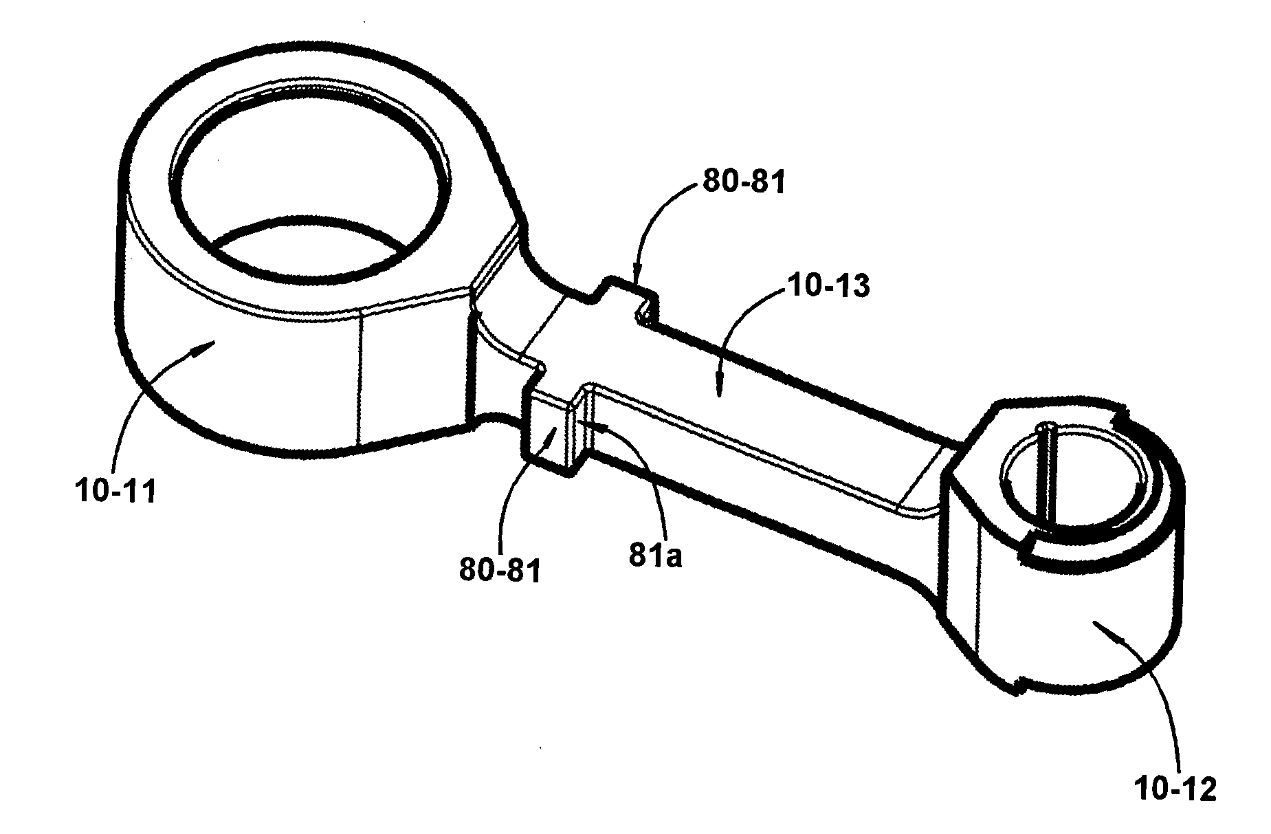
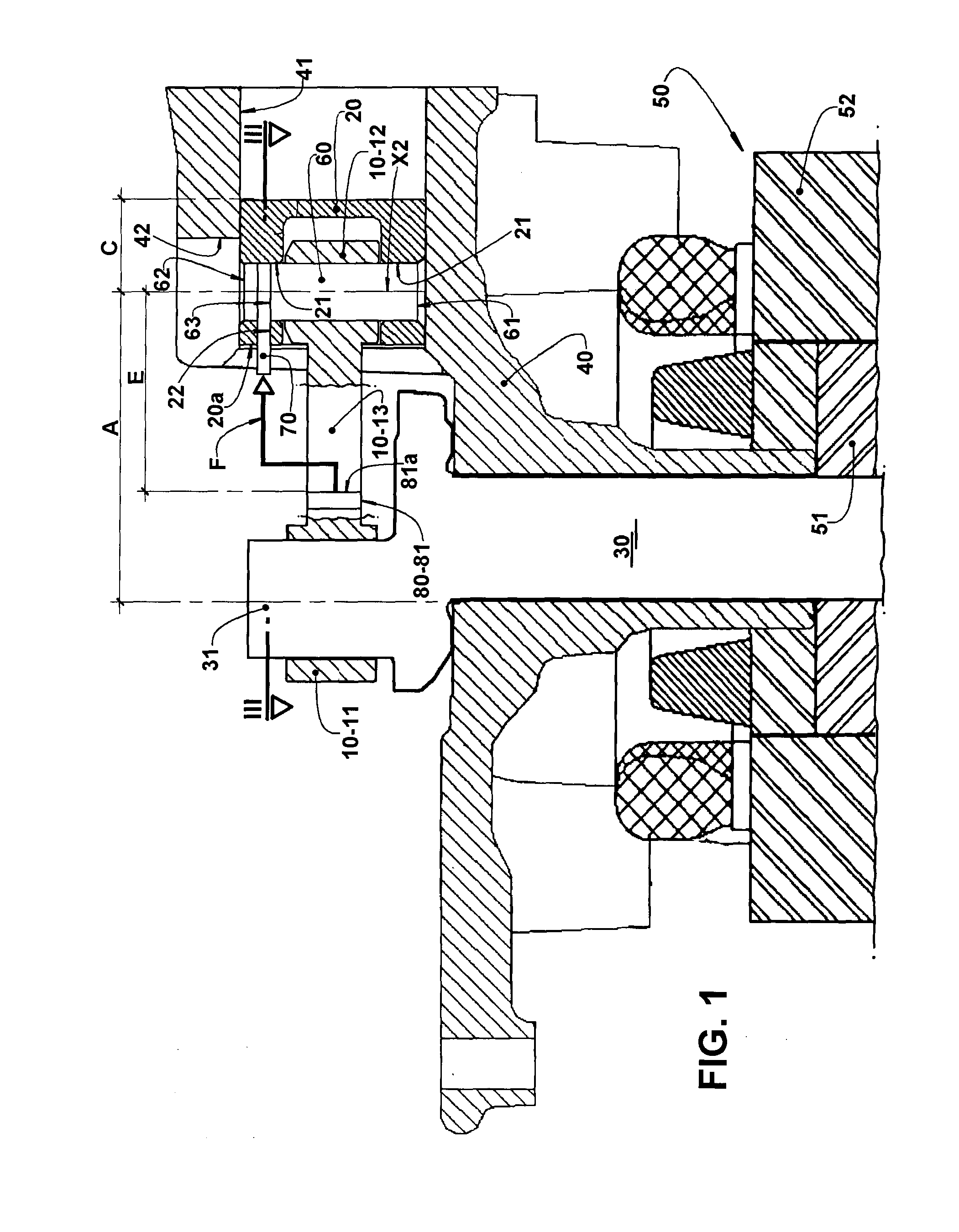
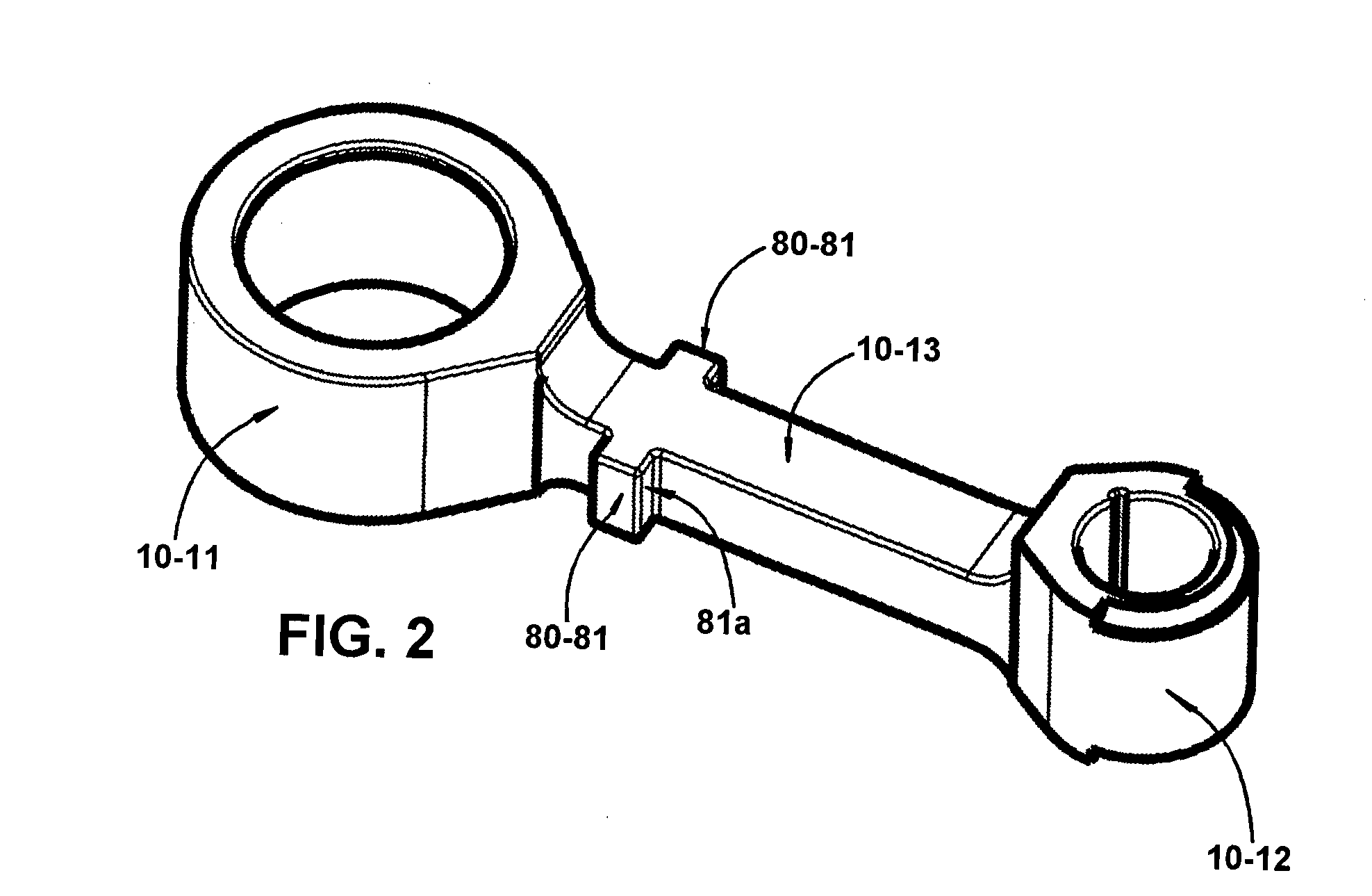
[0034]As illustrated and previously described, the present connecting rod 10 is of the single-piece type, having a larger eye 11 mounted around an eccentric portion 31 of a crankshaft 30 of a refrigeration compressor, and a smaller eye 12 to be coupled to a piston 20 of the compressor, said eyes being interconnected by a rod 13. The refrigeration compressor, to which the present connecting rod is designed to be applied, can be of the type which comprises a crankcase 40, which defines a cylinder 41, inside which the piston 20 is displaced by the connecting rod 10, in a reciprocating movement, when the crankshaft 30 is driven by an electric motor 50, which has its rotor 51 affixed to the crankshaft 30 and its stator 52 affixed to the crankcase 40, around the rotor 51.

[0035]The coupling of the smaller eye 12 of the connecting rod 10 to the piston 20 is obtained by means of a generally massive wrist pin 60. Said wrist pin 60 has its opposite end portions introduced, without interference...


PUM


Abstract

The compressors of the invention comprise: a crankcase carrying a cylinder, inside which is lodged a piston provided with two radial holes and with one eccentric axial hole; a connecting rod having a smaller eye mounted in the interior of the piston and connected to a larger eye through a rod; a wrist pin provided with a diametral hole and disposed through the smaller eye of the connecting rod and through the opposite radial holes of the piston; and an elastic pin to be inserted in the eccentric axial hole of the piston and in the diametral hole of the wrist pin. The connecting rod incorporates an indexing stop which defines an axial seating surface for a tool for inserting the elastic pin, said axial seating surface being positioned at a predetermined distance from the axis of the smaller eye of the connecting rod.

Description

FIELD OF THE INVENTION[0001]The present invention refers to a connecting rod for refrigeration compressors, of the reciprocating type, used in small household and commercial refrigeration systems and which comprise, in the interior of a shell, a crankcase which defines a cylinder, inside which reciprocates a piston, and a bearing hub, in which is supported a crankshaft incorporating an eccentric portion and carrying a rotor of an electric motor, whose stator is affixed to the crankcase. The connecting rod of the present invention comprise, in a single piece, a rod or web connecting a larger eye, mounted around the eccentric portion of the crankshaft, and a smaller eye which is affixed to a pin internal to the piston, so that the connecting rod can reciprocate the piston in the interior of the cylinder, when the crankshaft is rotated by the electric motor.PRIOR ART[0002]It has been continuous the search for solutions aiming at increasing the energy efficiency of the reciprocating com...

Claims


Application Information

Patent Timeline
IPC IPC(8): F16C7/02
CPCF16C7/02F04B39/0022F04B53/144F04B53/147F16C7/023F16C2362/52Y10T74/2144
Inventor SILVA, FABIANO DOMINGOSLONGO, GELSON
Owner WHIRPOOL SA
Learn More