Endoscopic system
a technology of endoscopic system and reflected light, applied in the field of endoscopic system, can solve the problems of difficult fusion and directivity produced by reflected light, and achieve the effect of reducing luminance differences
- Summary
- Abstract
- Description
- Claims
- Application Information
AI Technical Summary
Benefits of technology
Problems solved by technology
Method used
Image
Examples
example 1
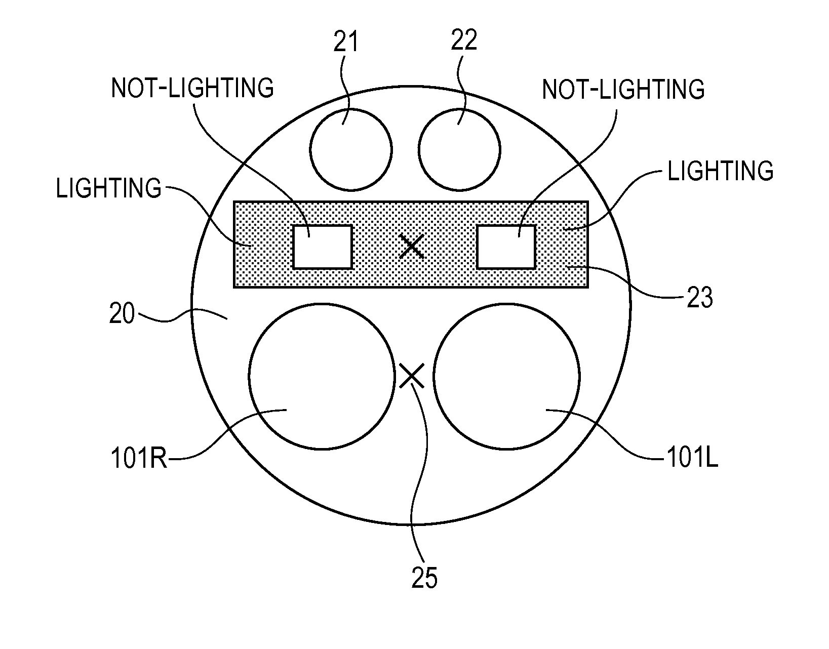
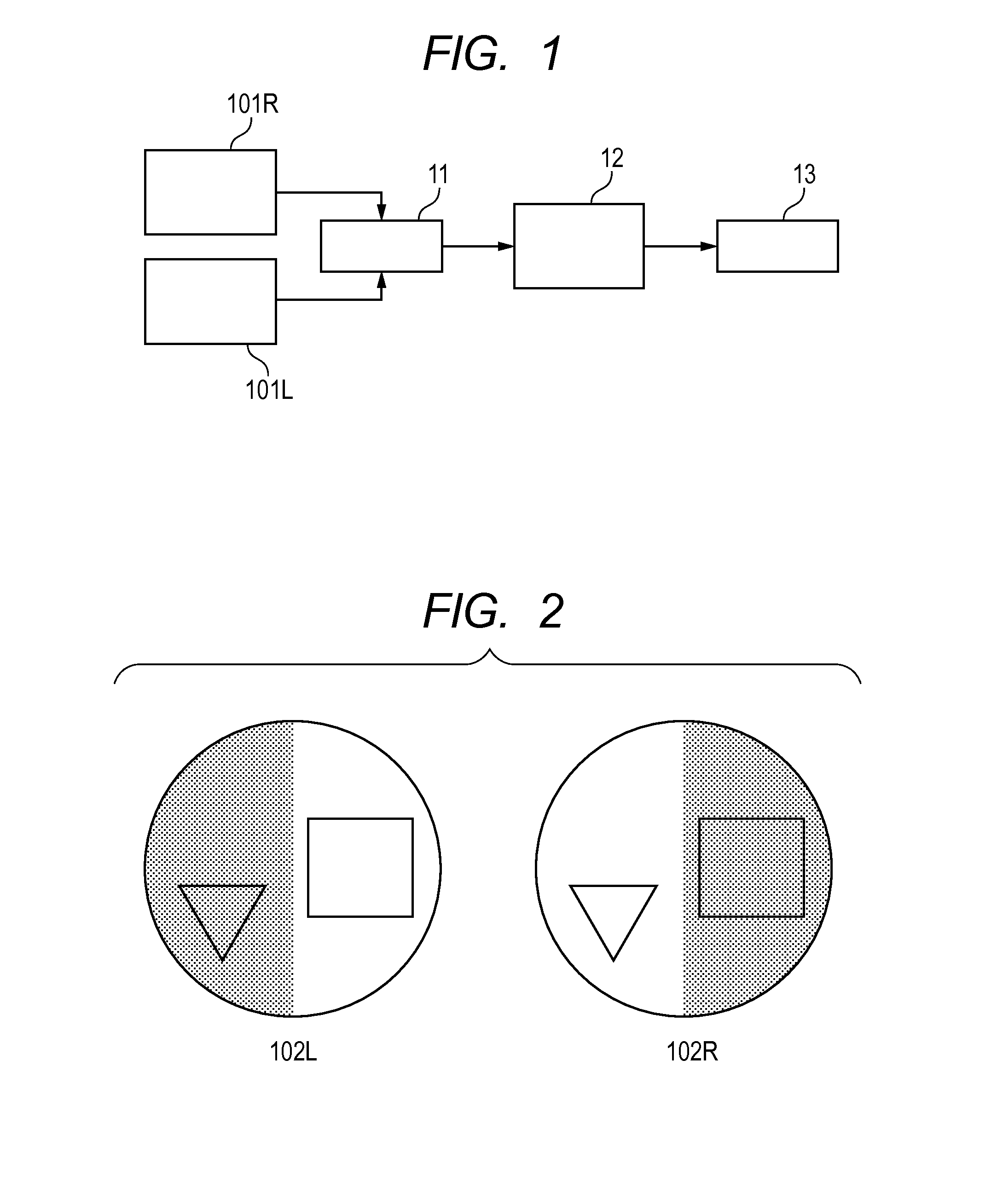
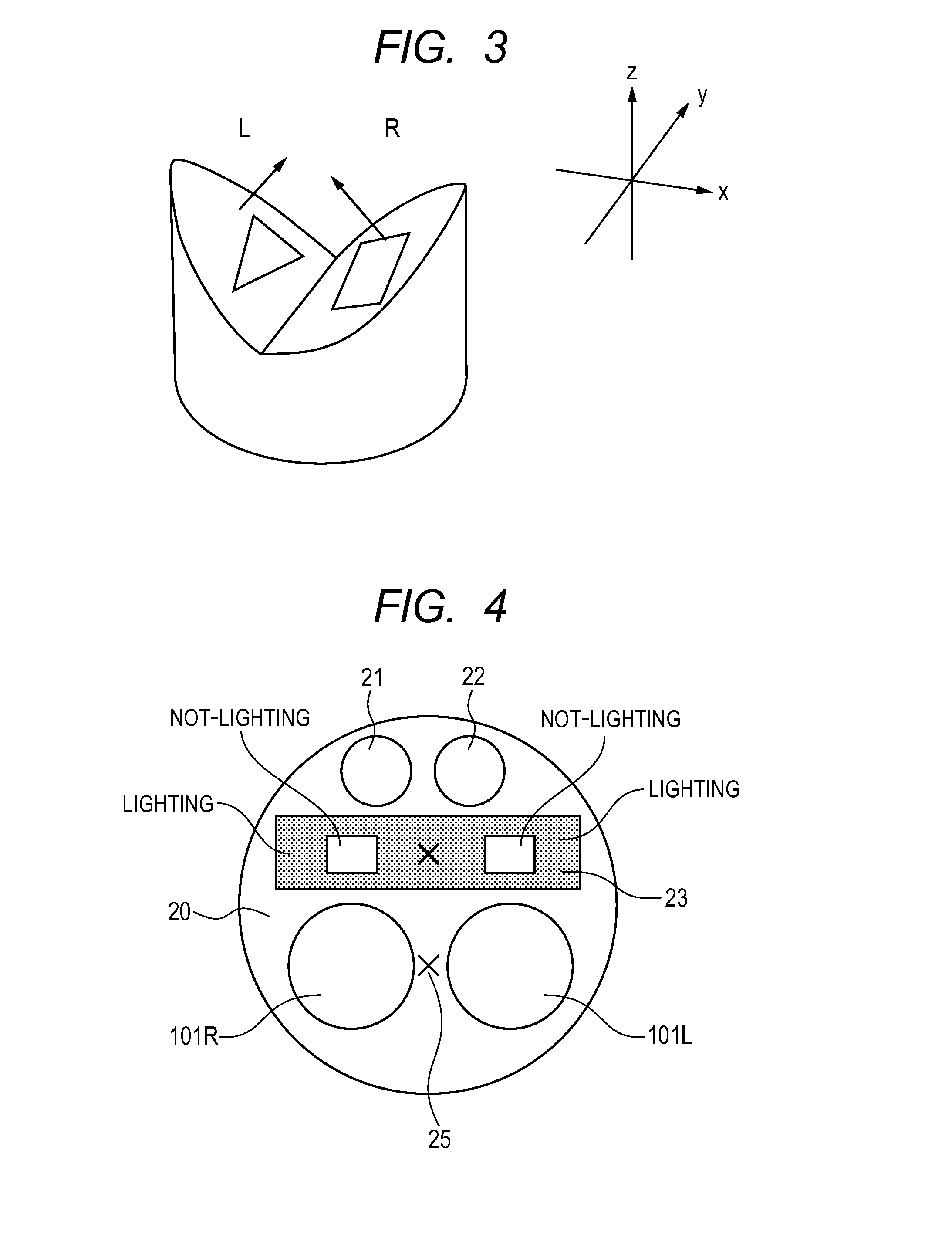
[0048]A distal part 20 of a stereoscopic endoscope in this example shown in FIG. 7 had channel holes 21 and 22 and an illumination window 23. In this example, the diameter of the endoscope was 10 mm, the diameter of the imaging systems 101R and 101L was 3 mm, the viewing direction angle was 70 degrees, the diameter of the channel holes 21 and 22 was 1.5 mm, and the illumination window was 1.5 mm high×8 mm wide. Also, an aperture angle (2θ) of an optical fiber used for illumination was 20 degrees. The endoscope was placed such that the imaging systems and illumination would be oriented in the z direction of an object under observation in FIG. 8, where the object was depressed from left and right toward a center of an observation region with the depression being inclined toward the near side, such as shown in FIG. 8. The object was observed from the near side without applying the present invention, and images obtained by the imaging systems 101R and 101L inserted through the channel h...
example 2
[0052]In this example, a specific area was processed according to the form of the subject. FIG. 13 shows an example of images obtained by observing an object from above through the same endoscope as in Example 1 using a light distribution such as shown in FIG. 7, the object under observation having a protrusion in part of its regions such as shown in FIG. 14. When brightness of regions A, B and C are compared between the image 102R and image 102L, it can be seen that only region A is brighter in the image 102L than in the image 102R whereas both regions B and C are almost equal in brightness between the two images. This is because the circumstance is such that reflected light from region A of the subject enters only the imaging system 101L. In this way, if there are differences in the luminance of some regions between images, the images do not mix properly when fused, and the object under observation might become indistinct.
[0053]In this example, by reducing directly reflected light...
example 3
[0054]This example relates to a mode of selecting a light distribution according to a form, surface conditions or the like of the subject. FIG. 17 shows an example of observation images obtained by observing an object through the same endoscope as in Example 1 using a light distribution such as shown in FIG. 10, the object under observation being depressed from left and right toward the center of an observation region inclined forward on the plane of the paper as in the case of Example 1. However, in this example, on the surface of the object under observation, a wavy irregularity structure was provided in the horizontal direction of the observation region. As shown in FIG. 17, the luminance distribution was almost the same between the image 102R and image 102L. However, in the tendency of luminance distribution, i.e., in the horizontal direction of the screen, the luminance distribution pattern coincided with a structural feature of the subject, i.e., the pattern of the wavy struct...
PUM
 Abstract
Description
Claims
Application Information
 - R&D
- Intellectual Property
- Life Sciences
- Materials
- Tech Scout
- Unparalleled Data Quality
- Higher Quality Content
- 60% Fewer Hallucinations
Browse by: Latest US Patents, China's latest patents, Technical Efficacy Thesaurus, Application Domain, Technology Topic, Popular Technical Reports.
© 2025 PatSnap. All rights reserved.Legal|Privacy policy|Modern Slavery Act Transparency Statement|Sitemap|About US| Contact US: help@patsnap.com


