Antenna control method and antenna device using the same

Active Publication Date: 2014-04-03
WISTRON NEWEB
View PDF1 Cites 4 Cited by
  • Summary
  • Abstract
  • Description
  • Claims
  • Application Information

AI Technical Summary

Benefits of technology

The present invention aims to improve antenna performance by controlling the way data is transmitted and received. The invention aims to reduce the time required to adjust the antenna, resulting in better performance and improved user experience.

Problems solved by technology

This kind of approach is time consuming and inconvenient.
Moreover, the antenna is very likely unable to have the best performance since the manual adjustment is coarse and subjective.

Method used


Image

  • Antenna control method and antenna device using the same
  • Antenna control method and antenna device using the same
  • Antenna control method and antenna device using the same

Examples


Embodiment Construction

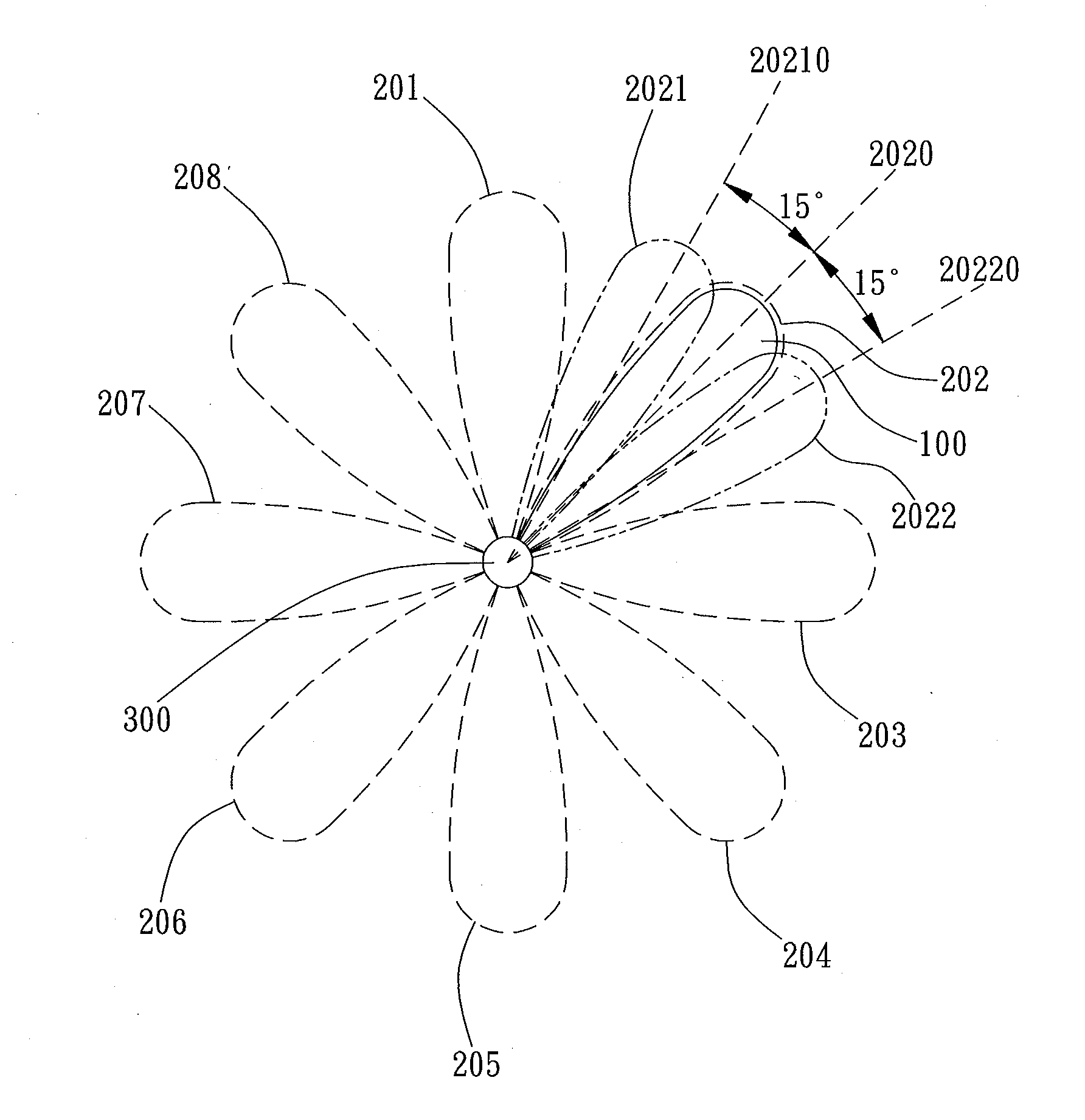
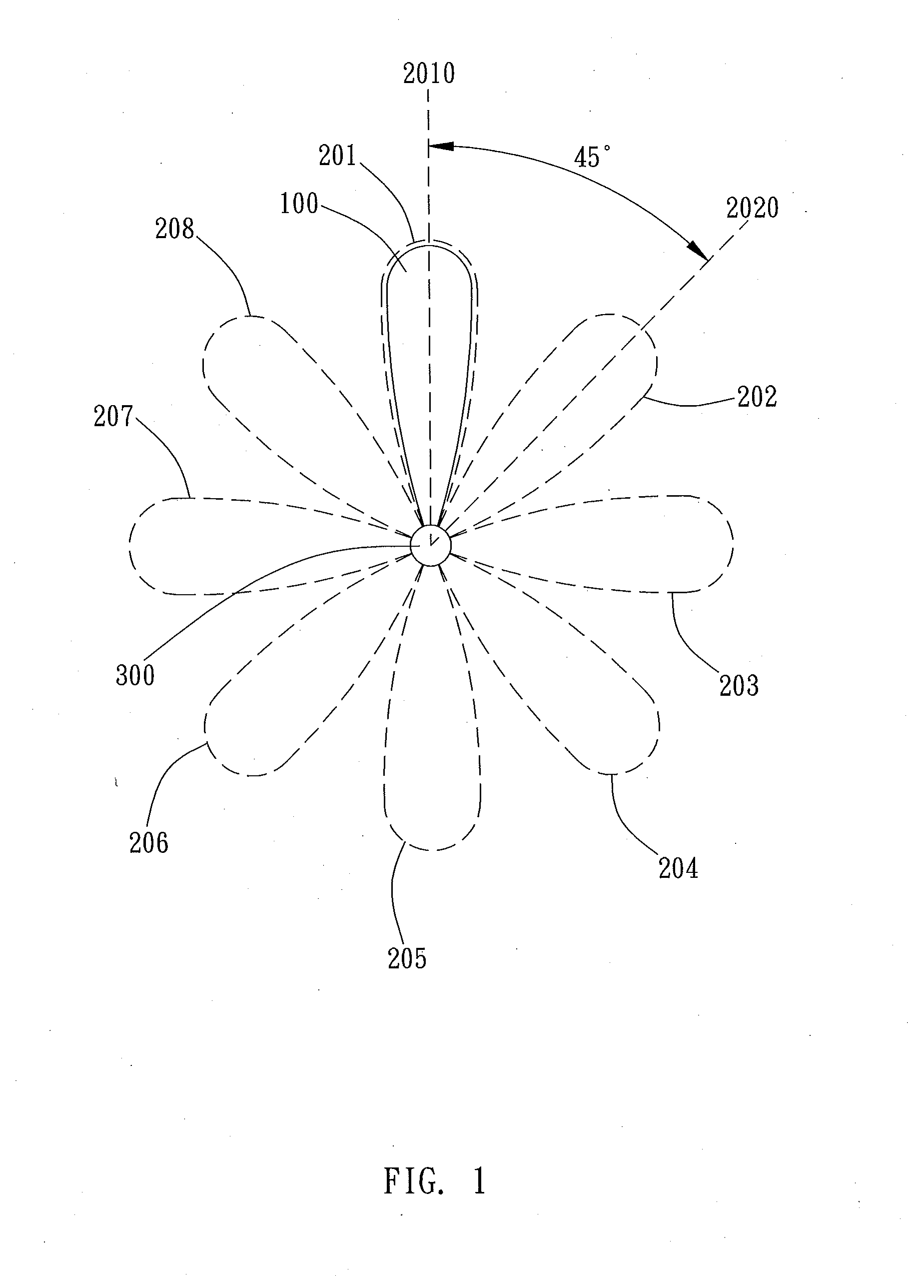
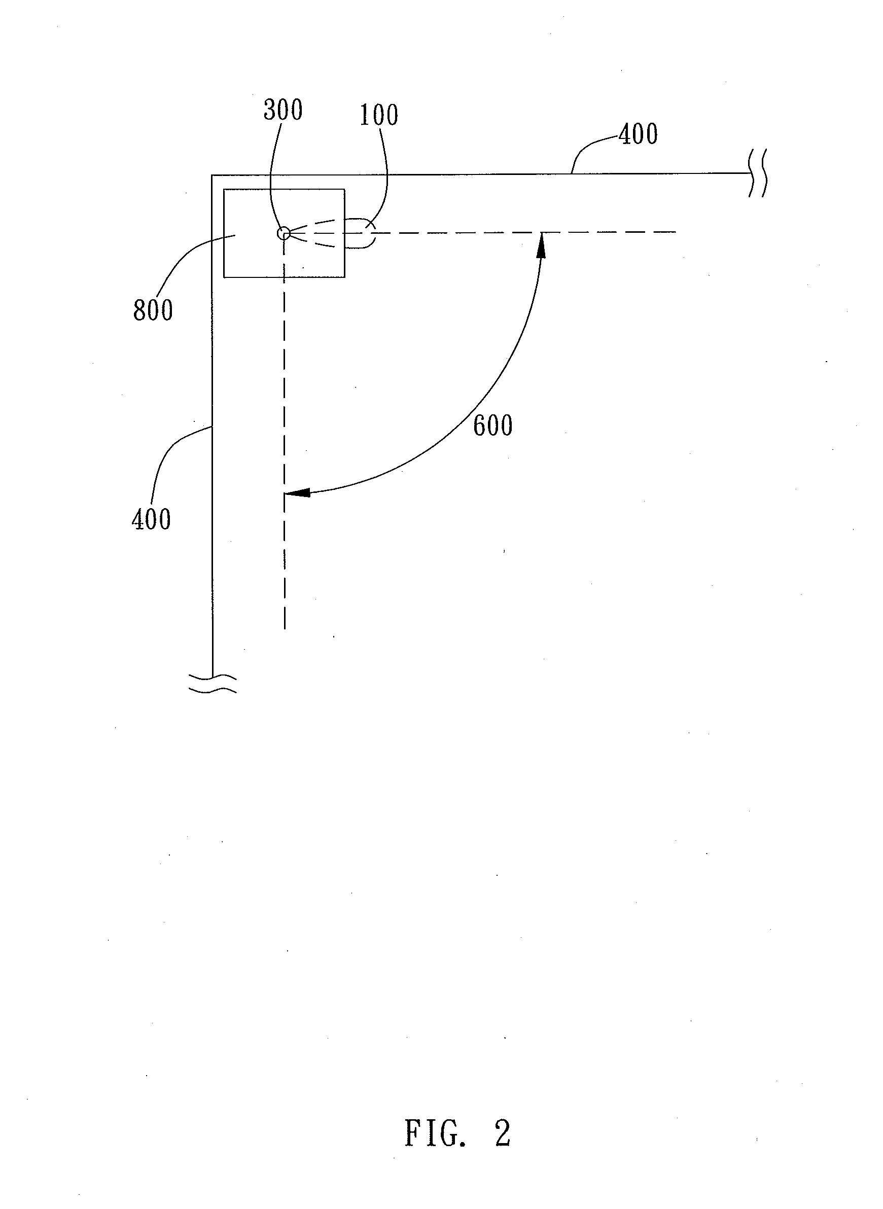
[0018]The antenna control method of the present invention is for use with an antenna, wherein the antenna is rotatable in a signal region. More particularly, as an embodiment shown in FIG. 1, the signal region includes a 360° all-angle area on a plane, wherein one end of an antenna 100 is connected to a rotation driving device 300 for rotating 360° in the signal region. In various embodiments, however, the signal is not limited to be a 360° all-angle area on a plane. As an embodiment shown in FIG. 2, the antenna device 800 having an antenna 100 is disposed in a corner formed by two walls 400. In this case, the signal region could be a 90° area 600 on a plane.

[0019]As shown in FIG. 3, the antenna control method of the present invention includes the following steps.

[0020]In step (A1), a plurality of rough scanning sectors in a signal region is defined. More particularly, as shown in FIG. 1, it is to define 8 rough scanning sectors, i.e. position 201, position 202, position 203, positi...


PUM


Abstract

The present invention provides an antenna control method and an antenna device. The method includes (A1) defining a plurality of rough scanning sectors in a signal region; (A2) rotating the antenna to each rough scanning sector to measure a first evaluation signal; (A3) selecting one of the plurality of rough scanning sectors in accordance with the first evaluation signals; (A4) defining a plurality of fine scanning sectors; (A5) rotating the antenna to the plurality of fine scanning sector corresponding to the selected rough scanning sector to measure a second evaluation signal; (A6) selecting one of the plurality of fine scanning sectors in accordance with the second evaluation signals; (A7) rotating the antenna to the selected fine scanning sector.

Description

BACKGROUND OF THE INVENTION[0001]1. Field of the Invention[0002]This invention generally relates to an antenna control method and an antenna device using the same.[0003]2. Description of the Prior Art[0004]Following with the progress of electronic technology, a variety of portable electronic devices are widely used in our daily life. For connecting the portable electronic devices to the network and increasing the transmitting / receiving ability to provide better communication quality, the type and design of an antenna of a network access point have been gradually emphasized.[0005]Rotary antennas are widely used because they are rotatable to adjust the direction of the antenna for making the antenna head toward a better direction having stronger signal and / or less interference to enhance the transmitting / receiving ability. However, users have to adjust the antenna to several directions manually, with many tries to find out the best direction. This kind of approach is time consuming an...

Claims


Application Information

Patent Timeline
IPC IPC(8): G01R29/10
CPCG01R29/10H01Q1/1257H01Q1/2291H01Q3/04
Inventor FANG, CHEN-HUNGHUANG, CHIH-WEILIN, WEN-JIUN
Owner WISTRON NEWEB
Why Eureka
Try Eureka