Quick release device for safety helmet

a safety helmet and quick release technology, applied in the direction of helmet covers, headwear fastening, protective garments, etc., can solve the problems of difficult use of latches and anchors by drivers, difficulty in attaching latches to anchors, and the inability to pull the latches off the surface of the helmet, etc., to achieve the effect of quick connection of the devi

Inactive Publication Date: 2014-04-03
NO LIMIT SAFETY
View PDF8 Cites 10 Cited by
  • Summary
  • Abstract
  • Description
  • Claims
  • Application Information

AI Technical Summary

Benefits of technology

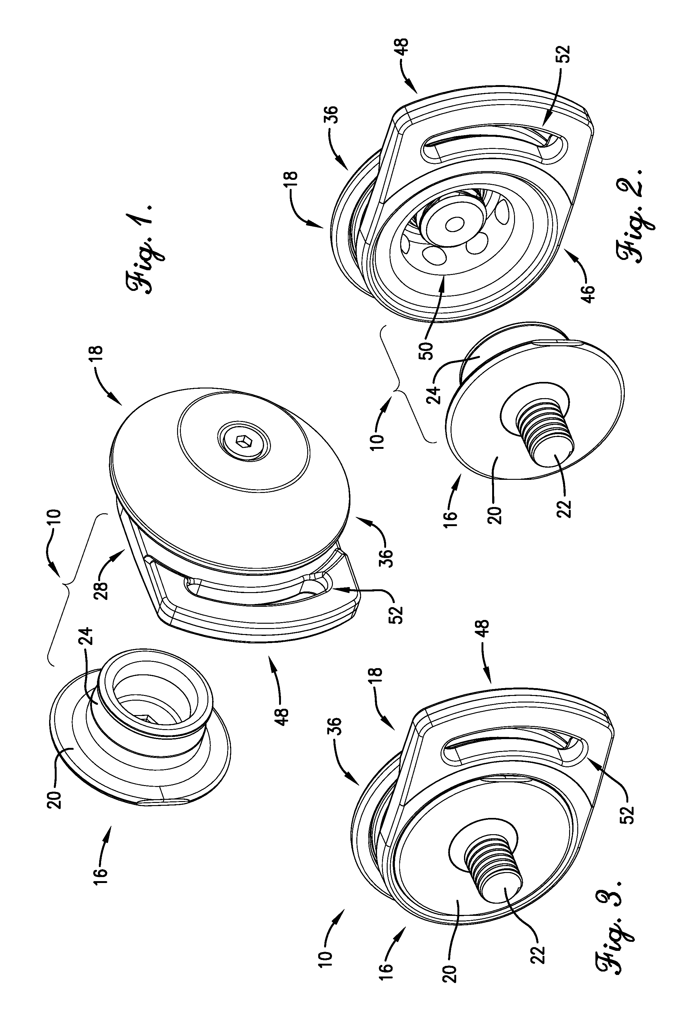
[0007]Embodiments of the current invention solve the above-mentioned problems by providing a quick release device for attaching a tether to a safety helmet. An embodiment of the device broadly comprises an anchor to couple to the helmet and a latch to couple to the tether. The anchor may include a cylindrical wall with a circumferential indentation. The latch is configured to be attached to and removed from the anchor and may include a barrel, a plurality of ball bearings, and a push-pull button. The barrel may include a sidewall in which the ball bearings are rigidly retained when the latch is in a locked state and the ball bearings are loosely retained when the latch is in a released state. The push-pull button may cover one end of the barrel and may be pushed to attached the latch to the anchor and pulled to remove the latch from the anchor. The quick release device provides an advantage over prior art devices because all the driver has to do is roughly align the latch on the anchor and then press the latch to attach it to the anchor. Thus, a driver can quickly connect the device even when he is wearing gloves.

Problems solved by technology

The latch cannot be pulled away from the surface of the helmet because the surface normal motion of the rails is blocked by the stud of the anchor.
This type of latch and anchor may be difficult for the driver to utilize because typically the driver is already wearing a helmet and gloves when attempting to tether the helmet to the HANS device.
Attaching the latch to the anchor is challenging because the driver has to align the circular or oval space of the latch with the stud.
Thus, this type of latch and anchor may present problems to the driver both when attaching the latch and when removing it.

Method used


Image

  • Quick release device for safety helmet
  • Quick release device for safety helmet
  • Quick release device for safety helmet

Examples


Embodiment Construction

[0026]The following detailed description of the invention references the accompanying drawings that illustrate specific embodiments in which the invention can be practiced. The embodiments are intended to describe aspects of the invention in sufficient detail to enable those skilled in the art to practice the invention. Other embodiments can be utilized and changes can be made without departing from the scope of the current invention. The following detailed description is, therefore, not to be taken in a limiting sense. The scope of the current invention is defined only by the appended claims, along with the full scope of equivalents to which such claims are entitled.

[0027]In this description, references to “one embodiment”, “an embodiment”, or “embodiments” mean that the feature or features being referred to are included in at least one embodiment of the technology. Separate references to “one embodiment”, “an embodiment”, or “embodiments” in this description do not necessarily ref...


PUM


Abstract

A quick release device comprises an anchor to couple to a safety helmet and a latch to couple to a tether. The anchor may include a cylindrical wall with an indentation circumferentially located thereon. The latch is configured to be attached to and removed from the anchor and may include a barrel, a plurality of ball bearings, and a push-pull button. The barrel may include a sidewall in which the ball bearings are rigidly retained when the latch is in a locked state and the ball bearings are loosely retained when the latch is in a released state. The push-pull button may cover one end of the barrel and may be pushed to attached the latch to the anchor and pulled to remove the latch from the anchor.

Description

BACKGROUND OF THE INVENTION[0001]1. Field of the Invention[0002]Embodiments of the current invention relate to automobile racing safety equipment. More particularly, embodiments of the current invention relate to a quick release device for attaching a tether to a safety helmet.[0003]2. Description of the Related Art[0004]A head and neck support (HANS) device is a structure that is worn around the neck and over the shoulders of a race car driver while racing. The driver's helmet is connected to the HANS device with a tether in order to reduce the likelihood or severity of head and / or neck injuries in the event of a crash or collision. The tethering of the helmet to the HANS device generally prevents extended forward motion of the helmet (and head) relative to the HANS device. The tether may slidably couple to the rear of a collar portion of the HANS device and generally allows the driver to rotate his head from side to side. The tether may include an elongated flat strap with two lat...

Claims


Application Information

Patent Timeline
Patent Type & Authority Applications(United States)
IPC IPC(8): A42B3/08
CPCA42B3/0473Y10T24/3424
Inventor TOM, DARNELLSANKO, NATHAN
Owner NO LIMIT SAFETY
Why Eureka
Try Eureka