
Organic layer deposition apparatus, organic light-emitting display apparatus, and method of manufacturing the organic light-emitting display apparatus

a technology of organic light-emitting display and organic layer, which is applied in the direction of vacuum evaporation coating, coating, thermoelectric devices, etc., can solve the problems of increasing the replacement of relative bulky display apparatuses with portable ones, difficult to form fine and minute patterns in the deposition process using the deposition mask, and difficult to perform an alignment of the substrate and the deposition mask

Active Publication Date: 2014-03-27
SAMSUNG DISPLAY CO LTD
View PDF9 Cites 29 Cited by
  • Summary
  • Abstract
  • Description
  • Claims
  • Application Information

AI Technical Summary

Benefits of technology

This patent describes improvements to an apparatus used to deposit layers of organic material, as well as to an organic light-emitting display apparatus and a method of manufacturing it. The improvements can enhance the quality of the deposited layers, resulting in better performance of the display apparatus.

Problems solved by technology

Recently, relatively bulky display apparatuses are increasingly being replaced with portable thin flat panel display apparatuses.
However, it is difficult to form a fine and minute pattern in the deposition process using the deposition mask.
In particular, as a size of the organic light-emitting display apparatus increases, it is difficult to perform an alignment of the substrate and the deposition mask, which makes it difficult to control a characteristic of a deposited layer, e.g., a minute pattern of the deposited layer.
In particular, because it is difficult to control movement of the substrate in a deposition apparatus, it is difficult to control the deposition process.
As a result, a characteristic of the deposition process deteriorates, to thus limit the improvement of the characteristic of the deposited layer.

Method used


Image

  • Organic layer deposition apparatus, organic light-emitting display apparatus, and method of manufacturing the organic light-emitting display apparatus
  • Organic layer deposition apparatus, organic light-emitting display apparatus, and method of manufacturing the organic light-emitting display apparatus
  • Organic layer deposition apparatus, organic light-emitting display apparatus, and method of manufacturing the organic light-emitting display apparatus

Examples


Embodiment Construction

[0062]Hereinafter, the present invention will be described in detail by explaining exemplary embodiments of the present invention with reference to the attached drawings.

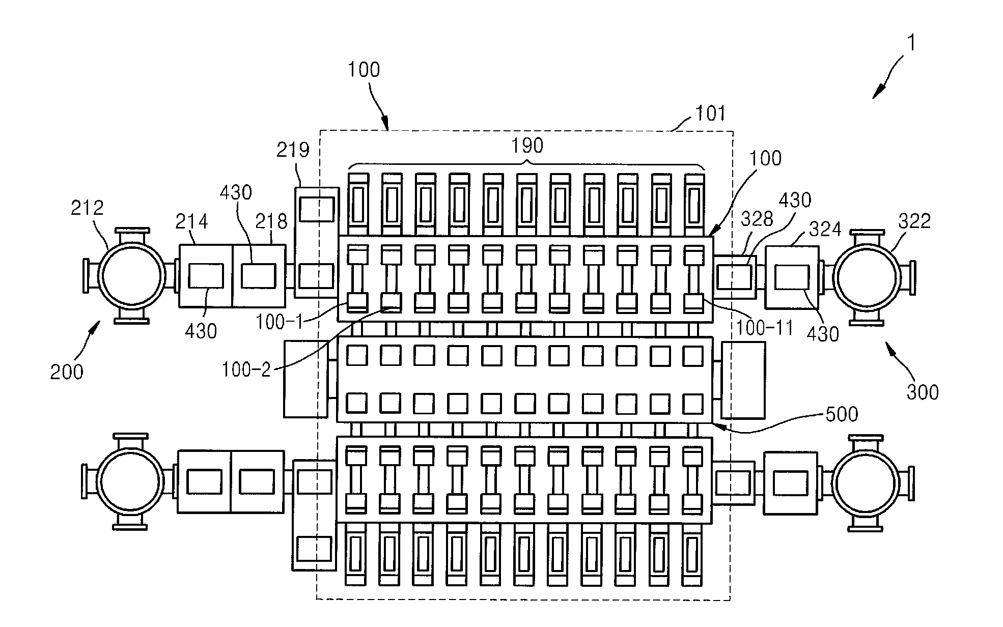
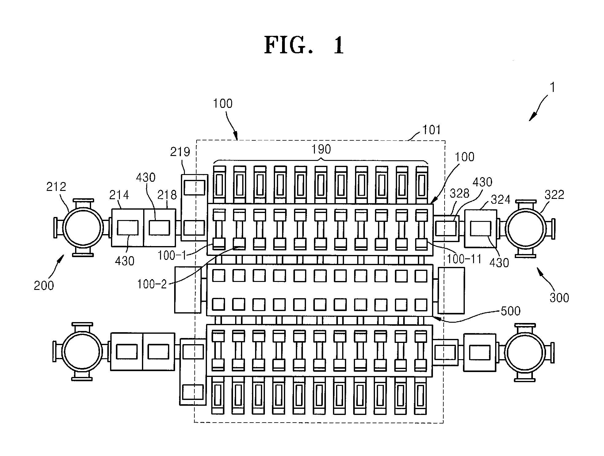
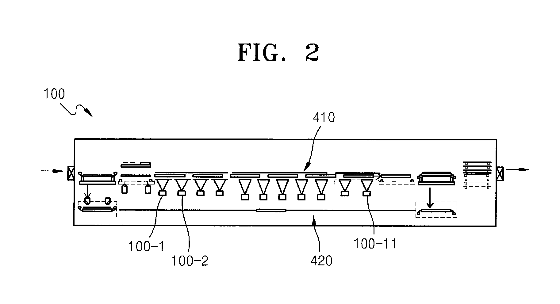
[0063]FIG. 1 is a schematic plan view illustrating a structure of an organic layer deposition apparatus 1 according to an embodiment of the present invention. FIG. 2 is a schematic side view of a deposition unit 100 of the organic layer deposition apparatus 1 of FIG. 1, according to an embodiment of the present invention.

[0064]Referring to FIGS. 1 and 2, the organic layer deposition apparatus 1 includes the deposition unit 100, a loading unit 200, an unloading unit 300, and a conveyer unit 400 (refer to FIGS. 3 and 4).

[0065]The loading unit 200 may include a first rack 212, a transport chamber 214, a first inversion chamber 218, and a buffer chamber 219.

[0066]A plurality of substrates 2 (refer to FIGS. 3 and 4) onto which a deposition material has not yet been applied are stacked up on the first rack 212. A transpor...


PUM

PropertyMeasurementUnit
sizeaaaaaaaaaa
temperatureaaaaaaaaaa
distanceaaaaaaaaaa

Abstract

An organic layer deposition apparatus includes a transfer unit; a first conveyer unit including a guide member having accommodation grooves, a first accommodation part, a second accommodation part, and a connection part that connects the first accommodation part to the second accommodation part; a second conveyer unit for moving the transfer unit without the substrate; a loading unit for fixing the substrate on the transfer unit; a deposition unit including a chamber and an organic layer deposition assembly; and an unloading unit for separating the substrate, wherein the first accommodation part of the guide member is located close to ground compared to the second accommodation part, and includes a lower member, an upper member, elastic members located between the lower and upper members. The substrate fixed on the transfer unit is spaced from the organic layer deposition assembly while being transferred by the first conveyer unit.

Description

CROSS-REFERENCE TO RELATED APPLICATION(S)[0001]This application claims priority to and the benefit of Korean Patent Application No. 10-2012-0105248, filed on Sep. 21, 2012, in the Korean Intellectual Property Office, the disclosure of which is incorporated herein in its entirety by reference.BACKGROUND[0002]1. Field[0003]The present invention relates to an organic layer deposition apparatus, an organic light-emitting display apparatus, and a method of manufacturing the organic light-emitting display apparatus.[0004]2. Description of the Related Art[0005]Recently, relatively bulky display apparatuses are increasingly being replaced with portable thin flat panel display apparatuses. Among the flat panel display apparatuses, organic light-emitting display apparatuses are self-emissive display devices having wide viewing angles and an excellent contrast ratio, and high response speeds, and thus, are regarded as next-generation display apparatuses.[0006]An organic light-emitting display ...

Claims


Application Information

Patent Timeline
Patent Type & Authority Applications(United States)
IPC IPC(8): H01L21/67H01L27/32H10K99/00
CPCH01L21/67011H01L27/3244H01L27/3258C23C14/042C23C14/24C23C14/50C23C14/568H01L21/67709H01L21/6776H10K71/166H10K59/12H10K59/124
Inventor JIN, YONG-HYUNLIM, JAE-HA
Owner SAMSUNG DISPLAY CO LTD
Learn More