Receiver circuit and associated method
- Summary
- Abstract
- Description
- Claims
- Application Information
AI Technical Summary
Benefits of technology
Problems solved by technology
Method used
Image
Examples
Embodiment Construction
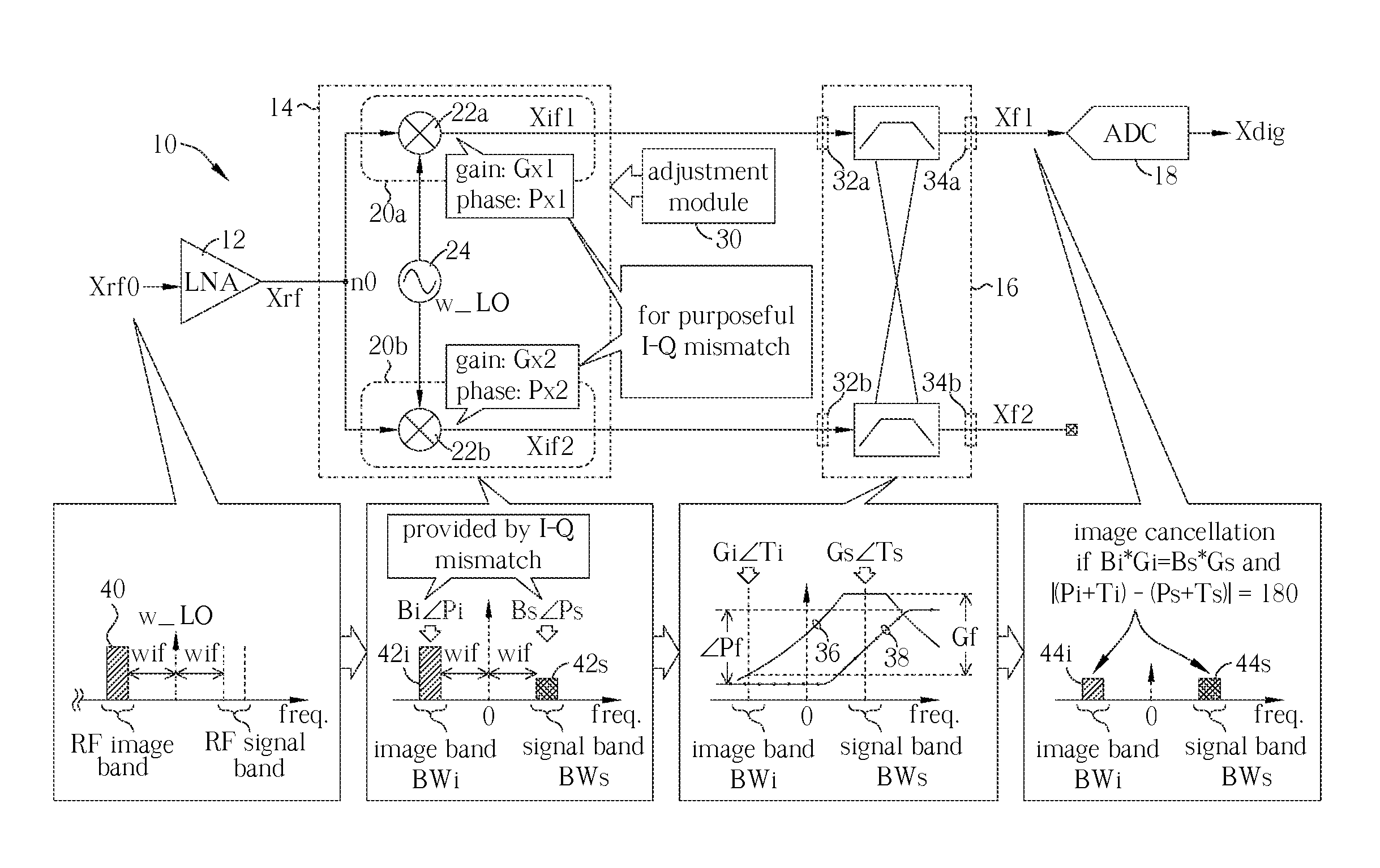
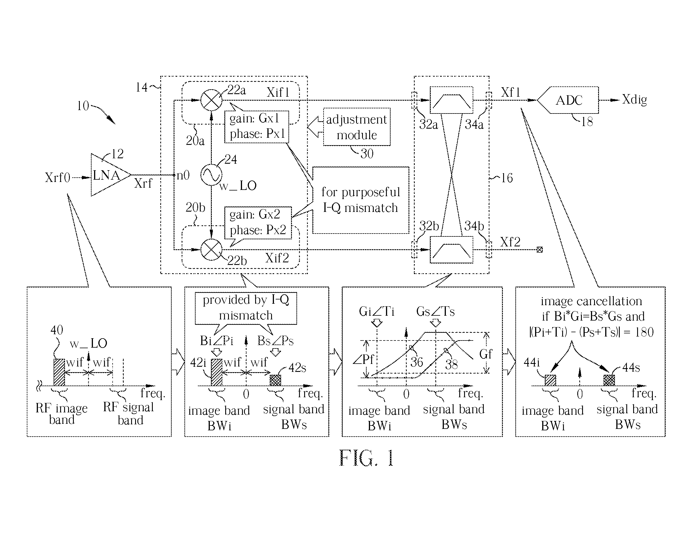
[0020]Please refer to FIG. 1 illustrating a receiver circuit 10 according to an embodiment of the invention; for example, the receiver circuit 10 can be a wireless RF receiver adopts low-IF receiving scheme. The receiver circuit 10 includes an amplifier 12 (e.g., a low-noise amplifier, LNA), a mixing block 14, an adjustment module 30, a filter 16 and an ADC 18. A signal Xrf0 received by the receiver circuit 10 is inputted to the amplifier 12 and amplified to a signal Xrf at a node n0. The mixing block 14 includes two mixing paths 20a and 20b; correspondingly, the filter 16, e.g., a complex band-pass filter, has two input terminals 32a and 32b, and two output terminals 34a and 34b. The mixing path 20a is coupled between the node n0 and the input terminal 32a, and the mixing path 20b is coupled between the node n0 and the input terminal 32b. The ADC 18 is coupled to the output terminal 34a.
[0021]In the mixing block 14, the mixing path 20a is arranged to translate frequency band of th...
PUM
 Abstract
Description
Claims
Application Information
 - R&D
- Intellectual Property
- Life Sciences
- Materials
- Tech Scout
- Unparalleled Data Quality
- Higher Quality Content
- 60% Fewer Hallucinations
Browse by: Latest US Patents, China's latest patents, Technical Efficacy Thesaurus, Application Domain, Technology Topic, Popular Technical Reports.
© 2025 PatSnap. All rights reserved.Legal|Privacy policy|Modern Slavery Act Transparency Statement|Sitemap|About US| Contact US: help@patsnap.com


