Tool string

a tool string and string technology, applied in the field of tool strings, can solve the problems that the couplings known do not provide the necessary connection between advanced tools and tool parts

Inactive Publication Date: 2014-03-20
WELLTEC AS
View PDF7 Cites 3 Cited by
  • Summary
  • Abstract
  • Description
  • Claims
  • Application Information

AI Technical Summary

Benefits of technology

[0016]Additionally, the connecting element may be arranged in a recess of one of the string parts, whereby the connecting element is prevented from substantially moving in the longitudinal direction.
[0017]Furthermore, the connecting element may be prevented from substantially moving in the longitudinal direction towards the first end by a protruding part of the string part having an increased outer diameter.

Problems solved by technology

However, known couplings do not provide the necessary connection between advanced tools and tool parts.

Method used


Image

  • Tool string
  • Tool string
  • Tool string

Examples


Embodiment Construction

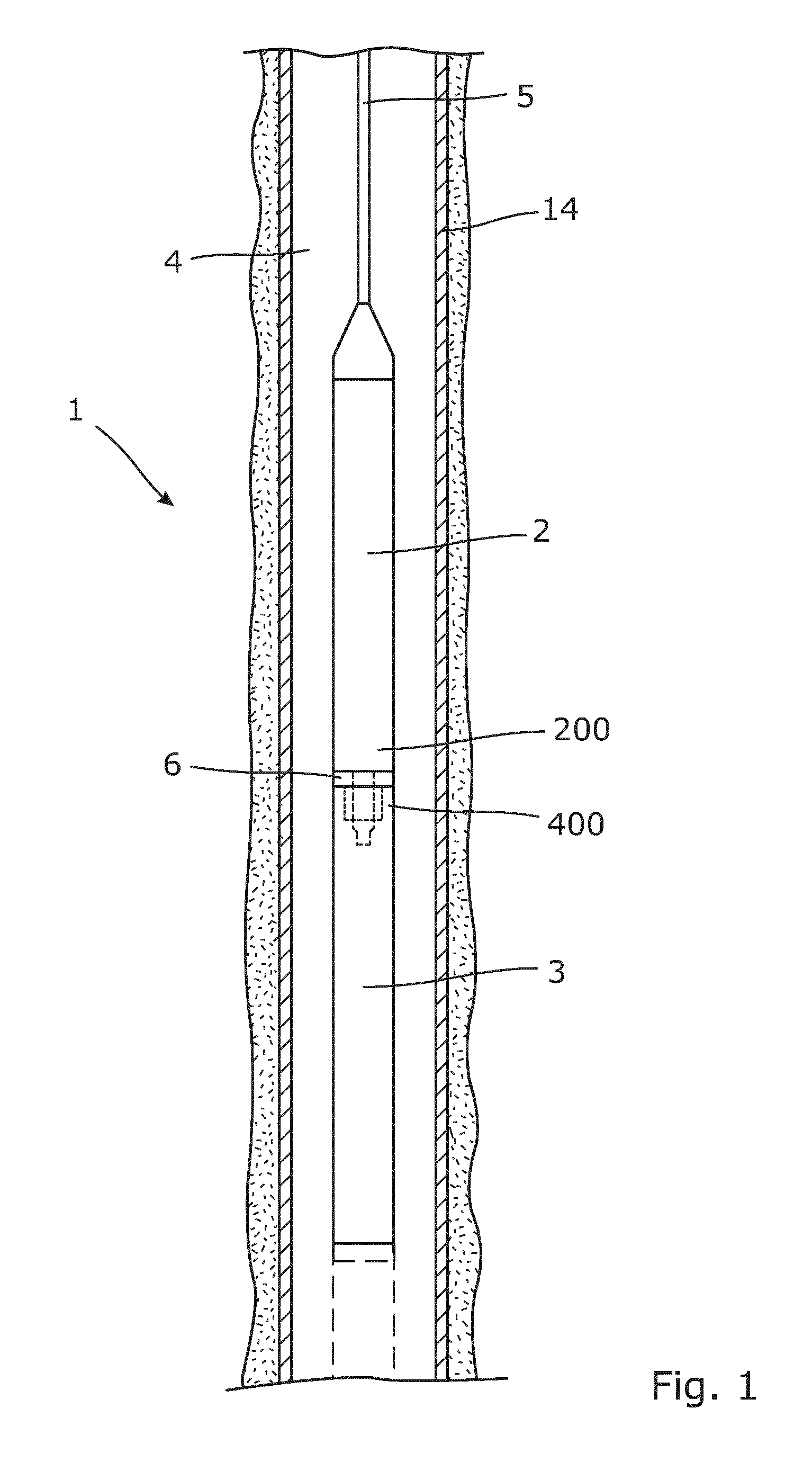
[0035]FIG. 1 shows a tool string 1 being suspended in a well 4 from a wireline 5. The tool string 1 may also be suspended using coiled tubing or by being part of a drill string. The shown well comprises a casing 14, but the tool string 1 may also be used in an uncased well.

[0036]The tool string 1 extends in a longitudinal direction and comprises at least a first tool string part 2 and a second tool string part 3. A first end 200 of the first string part 2 and a first end 400 of the second string part 3 are connected via a connecting element 6 arranged between the two string parts 2, 3 in the longitudinal direction. The dotted lines in FIG. 1 illustrate how part of the first end 200 of the first string part extends through the connecting element 6 and into the first end 400 of the second string part.

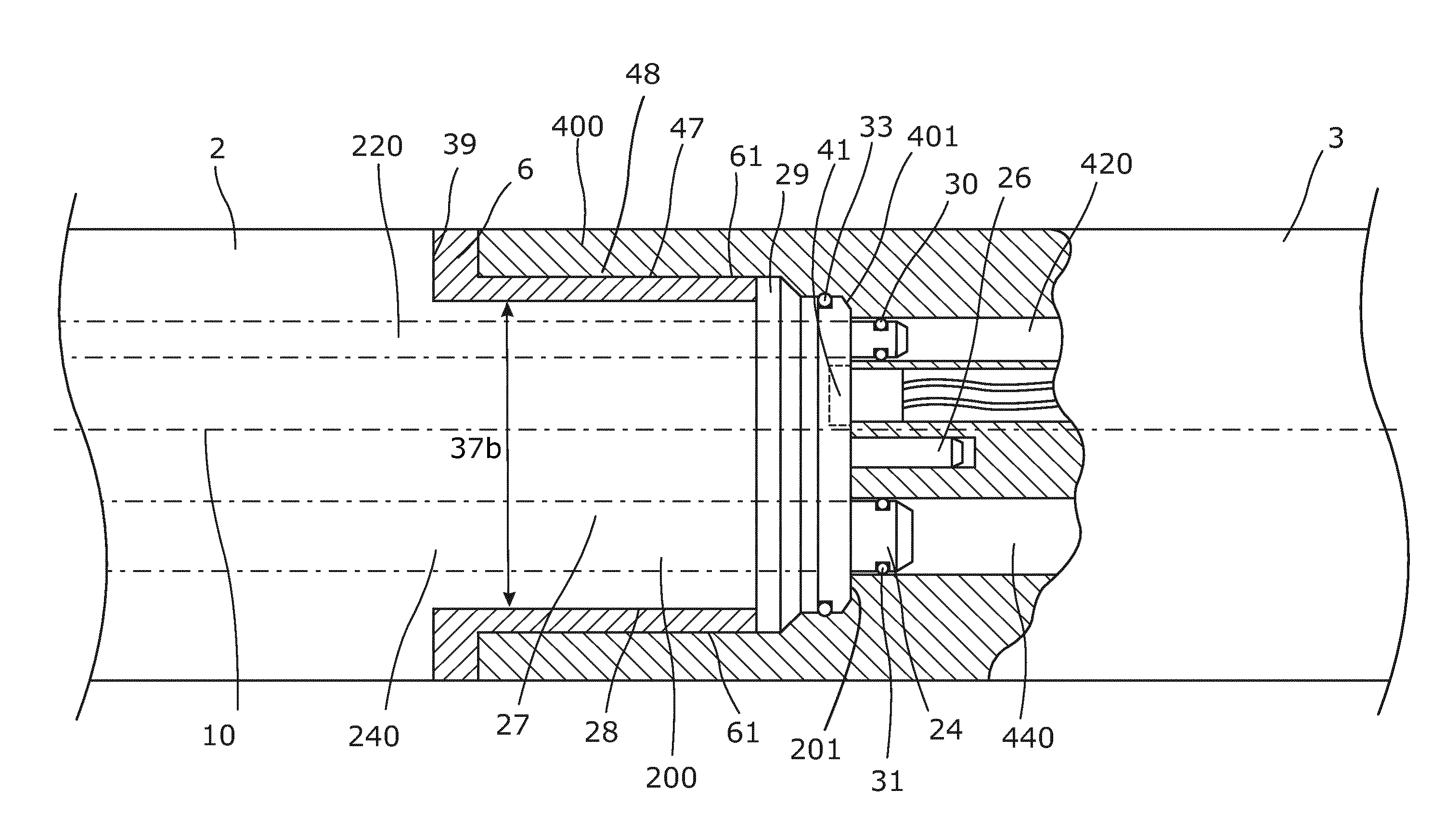
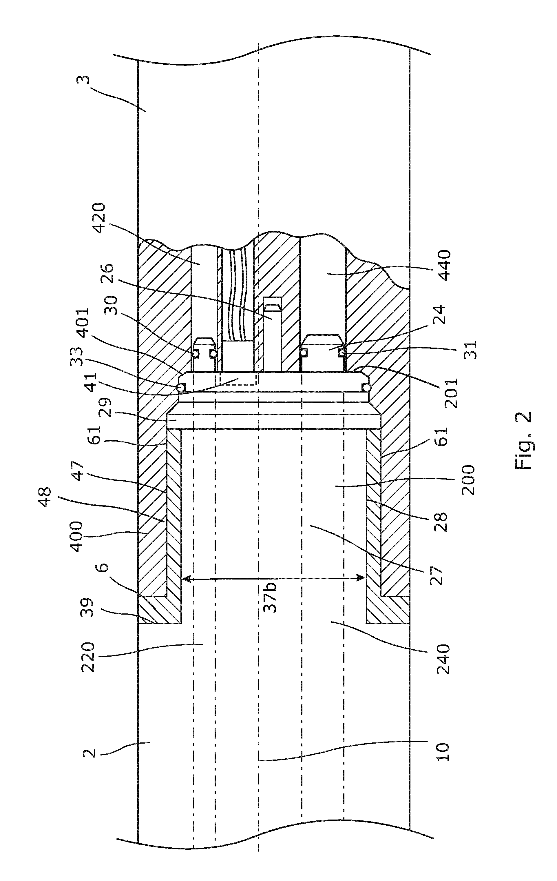
[0037]Referring to FIG. 2, the connection shown in FIG. 1 between the first string part 2 and the second string part 3 will be described in further detail below. For the purpose of clarit...


PUM


Abstract

The present invention relates to a tool string for being suspended in a well, the tool string extending in a longitudinal direction and comprising a first string part and a second string part, each having a centre axis and comprising; an electrical connection in a first end and a fluid channel extending at least partly through the string part. Furthermore, the tool string comprises a connecting element rotatably connected to one string part and adapted to be threadably connected to a threaded portion of the other string part to join the electrical connections of the first and second string parts. Furthermore, the present invention relates to a method for assembling two string parts of a tool string by rotating a connecting element.

Description

FIELD OF THE INVENTION[0001]The present invention relates to a tool string for being suspended in a well, the tool string extending in a longitudinal direction and comprising a first string part and a second string part, each having a centre axis and comprising; an electrical connection in a first end, and a fluid channel extending at least partly through the string part. Furthermore, the present invention relates to a method for assembling two string parts of a tool string.BACKGROUND ART[0002]The extraction rate from hydrocarbon-producing wells and the surrounding formations is becoming increasingly important due to decreasing oil reserves. Therefore, increasingly advanced tools are being developed and deployed in the search for and extraction of oil and gas. Tools deployed downhole in a well are often assembled or joined in a tool string comprising multiple tools, such as driving tools for driving the tool string forward in inclining sections of the well and / or operational tools f...

Claims


Application Information

Patent Timeline
Patent Type & Authority Applications(United States)
IPC IPC(8): E21B17/02E21B17/18
CPCE21B17/18E21B17/028E21B17/02
Inventor HALLUNDB.AE BUTTED.K, JORGEN
Owner WELLTEC AS
Why Eureka
Try Eureka