
Platform deck installation and removal method and apparatus

a platform and installation method technology, applied in special-purpose vessels, drilling pipes, transportation and packaging, etc., can solve the problems of high operational costs of lifting vessels, shortening the time of float-over techniques, and requiring large-scale lifting of vessels

Inactive Publication Date: 2014-03-13
BOA MARINE SERVICES
View PDF2 Cites 4 Cited by
  • Summary
  • Abstract
  • Description
  • Claims
  • Application Information

AI Technical Summary

Benefits of technology

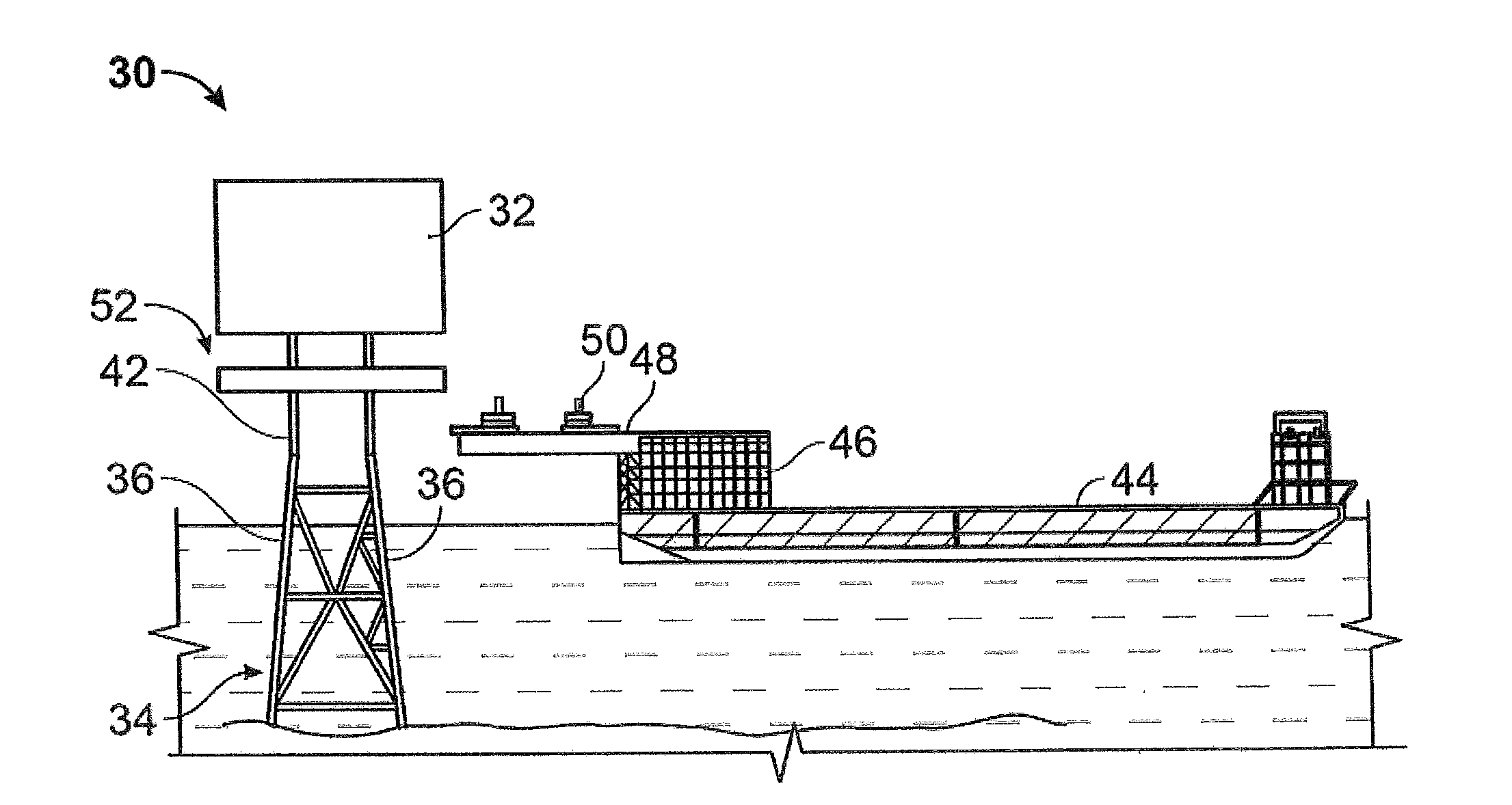
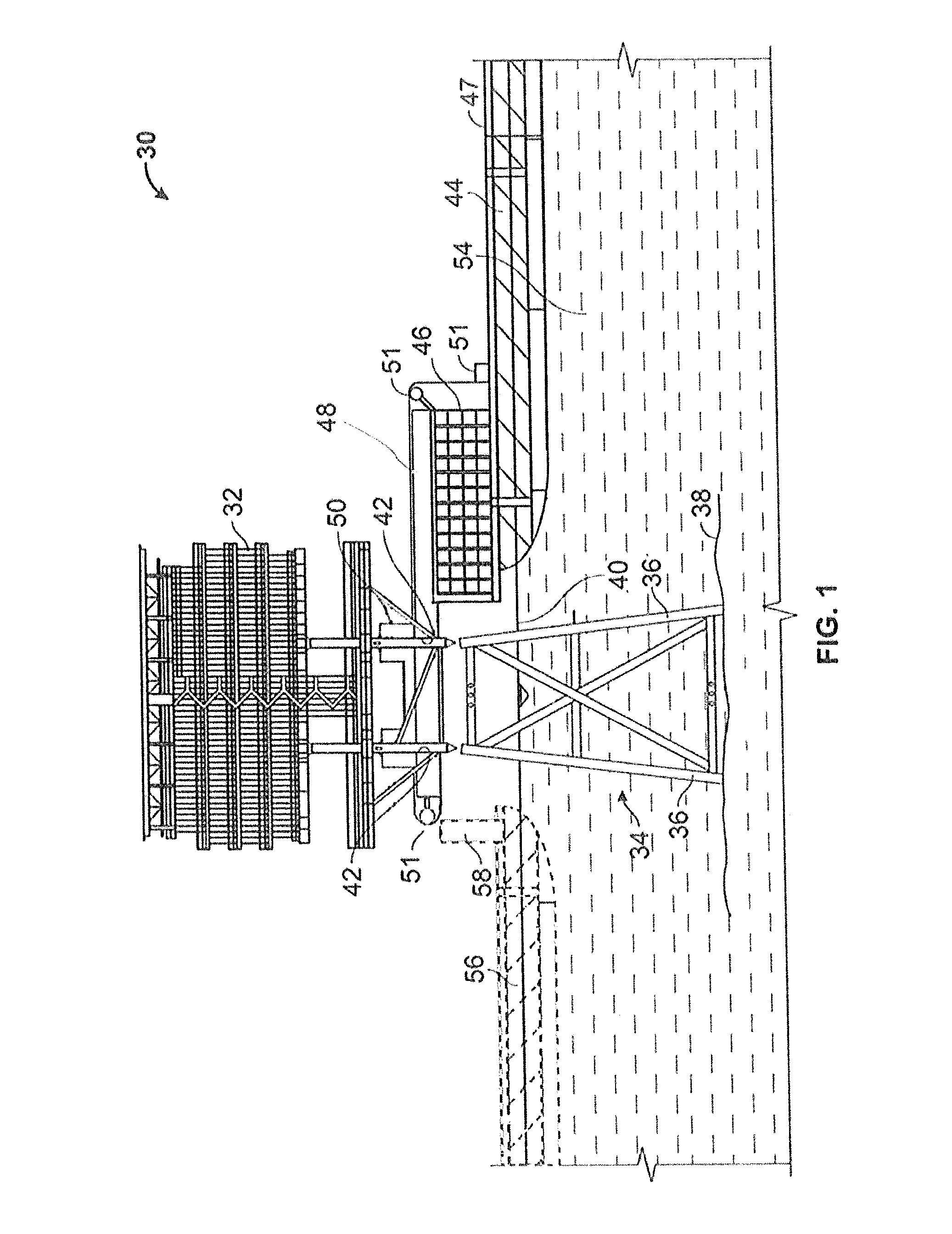
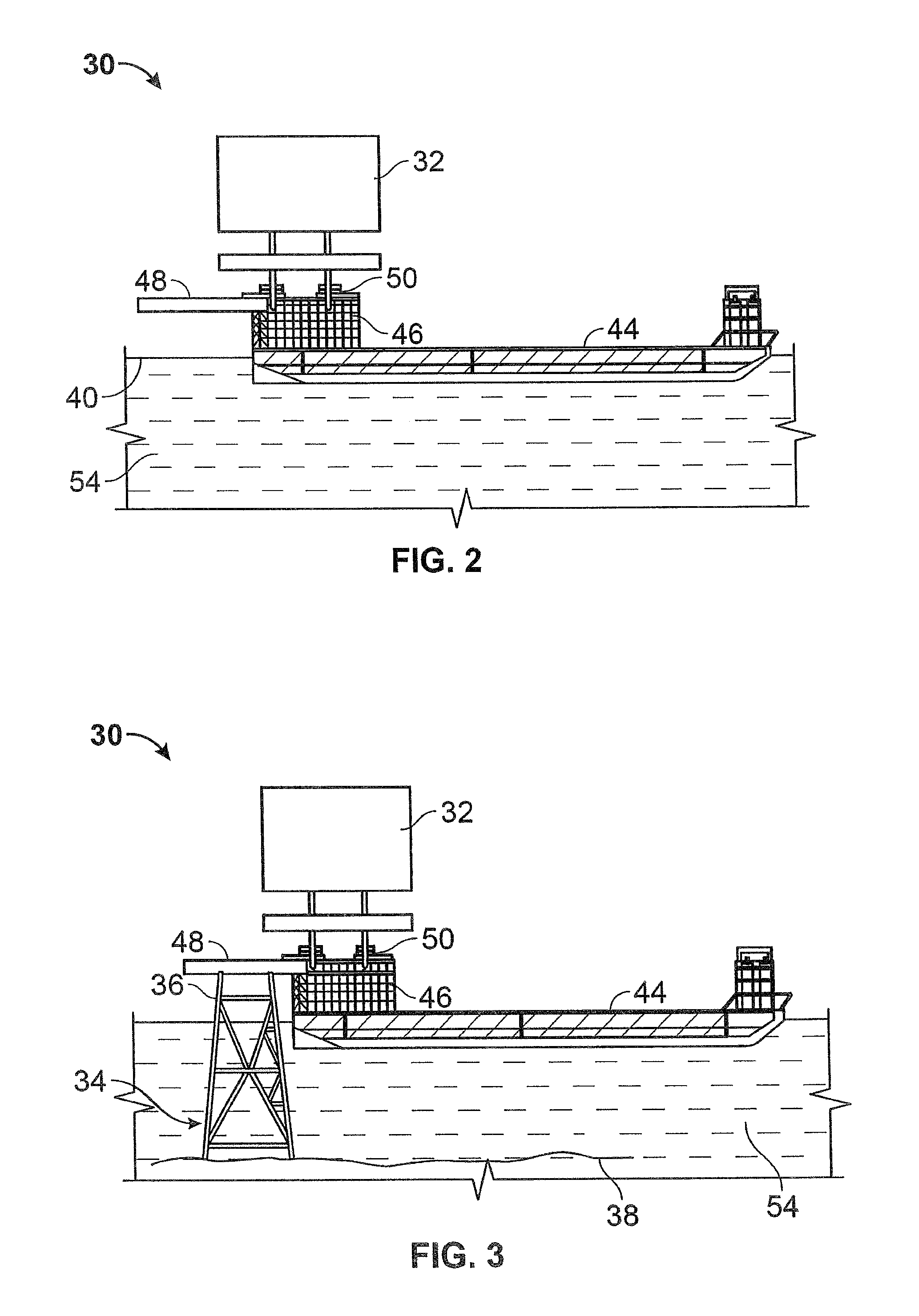
The present invention provides an apparatus and methods for attaching a topside to a substructure such as a jacket. This new way allows the topside to be loaded onto a marine vessel without touching the jacket, which can prevent damage or contamination. The apparatus includes a projecting structure and a support beam to hold the topside in place while attachment or detachment occurs. The invention has applications in the oil and gas industry and can be used in various ways to safely and efficiently install and remove topsides from jackets.

Problems solved by technology

However, the use of heavy lifting vessels presents a variety of challenges including the reliability of being able to safely lift heavy structures, the availability of vessels capable of lifting required amounts of weight.
High operational costs of using lifting vessels have encouraged the oil gas exploration and production industry to look for alternative ways to load heavy structures onto platforms.
Furthermore, float-over techniques can require shorter time and the weather window for performing such operations is wider than what is required in heavy lifting techniques.
However, the use of float-over technology is not without its drawbacks.
However, this is not favored for small platforms since the advantages of cost-efficiency disappear.
However, many older jackets or ones that are traditionally designed may not have legs wide enough to accept the single barge.
As such, they present additional difficulties in using a single barge or vessel with the float-over technique.

Method used


Image

  • Platform deck installation and removal method and apparatus
  • Platform deck installation and removal method and apparatus
  • Platform deck installation and removal method and apparatus

Examples


Embodiment Construction

[0037]The invention will now be described with reference to the drawing figures, in which like reference numerals refer to like parts throughout. An embodiment in accordance with the present invention provides a method and apparatus for loading a topside onto a jacket or other similar structure and also unloading a topside from a jacket. In some embodiments, the installation and removal techniques may be used for fixed platform topsides weighing up to 4000 mt.

[0038]The apparatus and methods described herein fall primarily within two embodiments using skid-on techniques. In a first embodiment, a pair of skid beams are used to carry the topside over the jacket legs. In the other embodiments, sponsons are attached to a barge or other vessel and extend out of from the barge or vessel. In the embodiments, the skid beams or the sponsons carry the topside over the jacket legs. The mating process of the topside to the jacket legs is similar to that used in the known float-over at site techn...


PUM


Abstract

An apparatus for loading a topside onto a jacket is provided. The apparatus may include: a projecting structure extending beyond a deck of a marine vessel wherein the projecting structure configured to support the topside and the projecting structure is dimensioned sufficiently long enough to allow the marine vessel to approach a submerged jacket and position the topside above the submerged jacket without having the marine vessel contact the jacket; and a support configured to support the topside above the projecting structure. A method for one of installing and removing a topside from a jacket may be provided. The method may include: positioning sponsons attached to a marine vessel around a jacket; supporting at least part of the weight of the topside on the sponsons; and one of attaching and detaching the topside and jacket.

Description

FIELD OF THE INVENTION[0001]The present invention relates generally to a method and apparatus for loading heavy offshore oiling equipment onto a submerged support such as a jacket. More particularly, the present invention relates to a method and apparatus for loading a topside onto and / or off a jacket.BACKGROUND OF THE INVENTION[0002]As the demand for oil continues to increase, more and more oil fields are being identified as beneath the ocean floor. Traditionally, with offshore oil production platforms, either fixed or floaters, the topsides are installed to the substructures, jackets or hull, by a specially designed heavy lifting vessel such as a crane vessel. However, the use of heavy lifting vessels presents a variety of challenges including the reliability of being able to safely lift heavy structures, the availability of vessels capable of lifting required amounts of weight. Strict environmental requirements can create narrow weather windows in which operations may be done. Hi...

Claims


Application Information

Patent Timeline
Patent Type & Authority Applications(United States)
IPC IPC(8): E02B17/08E02B17/04
CPCE02B17/00E02B17/08E02B2017/0043E02B2017/006E02B17/04E02B2017/0052B63B35/003E02B2017/0047
Inventor LIU, GENGSHENRORAAS, HELGE
Owner BOA MARINE SERVICES
Learn More