Eureka AIR delivers breakthrough ideas for toughest innovation challenges, trusted by R&D personnel around the world.

Anti-reflective device with attachment means for optical products

an anti-reflective device and optical technology, applied in the field of anti-reflective devices, can solve the problems of preventing the fit of the anti-reflective device in any particular product, unable to provide an anti-reflective device that can both fit different size products, and unable to provide an anti-reflective device that can fit different sizes of products

Inactive Publication Date: 2014-03-13
CARSON OPTICAL
View PDF6 Cites 4 Cited by
  • Summary
  • Abstract
  • Description
  • Claims
  • Application Information

AI Technical Summary

Benefits of technology

The invention provides a way to securely attach an anti-reflective device to an optical product without causing any damage or compromising its quality. This can be done by simply releasing either side of the attachment method.

Problems solved by technology

The technical problem addressed in this patent text is the limitations placed on currently available anti-reflective devices for riflescopes due to their small size and narrow focus. Current devices require precise positioning during installation and cannot easily accommodate different sized or supplied optics. Additionally, they often have difficulty attaching securely to the host optic while maintaining optimal performance. The new invention solves these issues by providing a rotatable connection between the anti-reflective device and the optic, making it easy to install and remove regardless of changes in the objectives' size or angle.

Method used


Image

  • Anti-reflective device with attachment means for optical products
  • Anti-reflective device with attachment means for optical products
  • Anti-reflective device with attachment means for optical products

Examples


Embodiment Construction

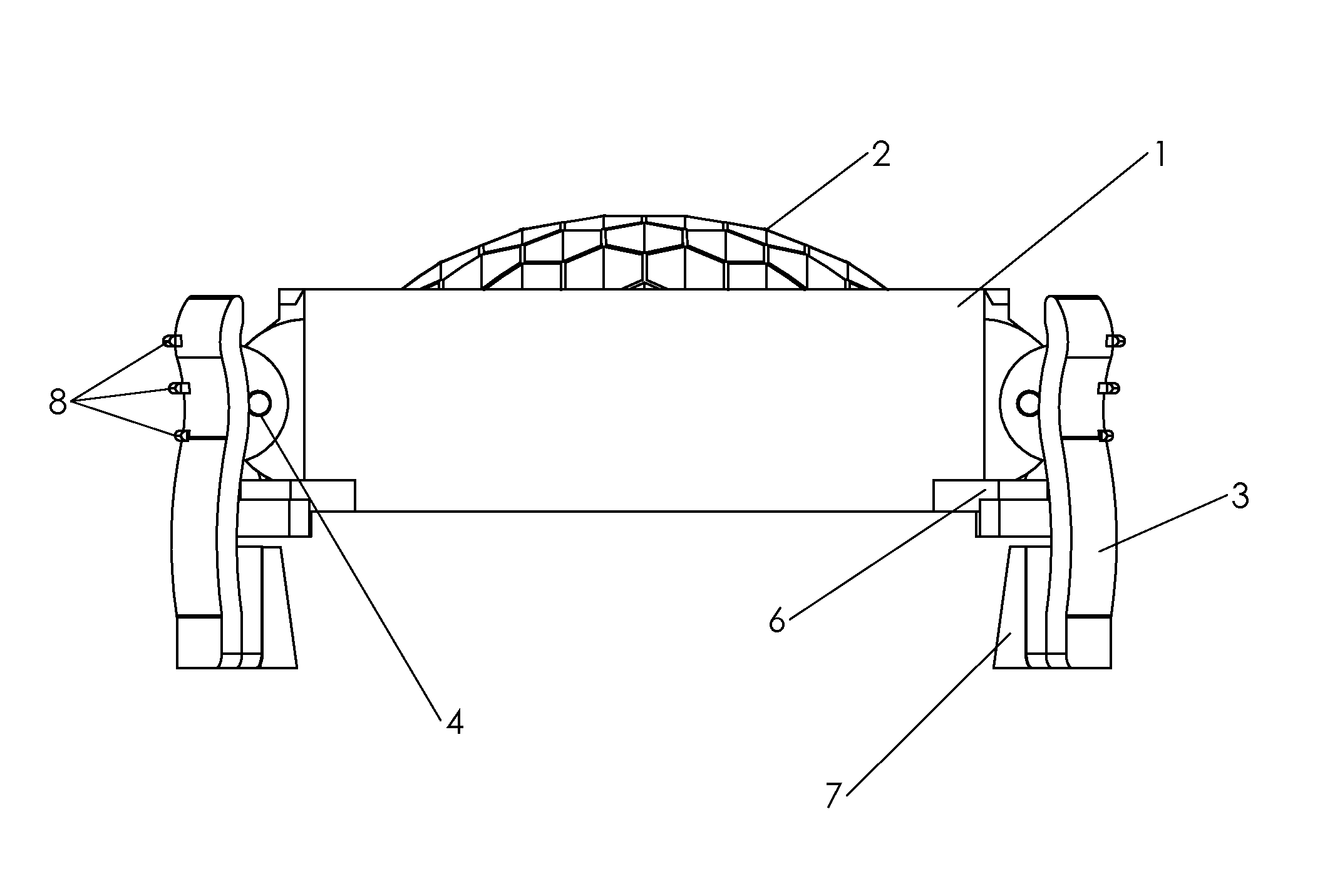
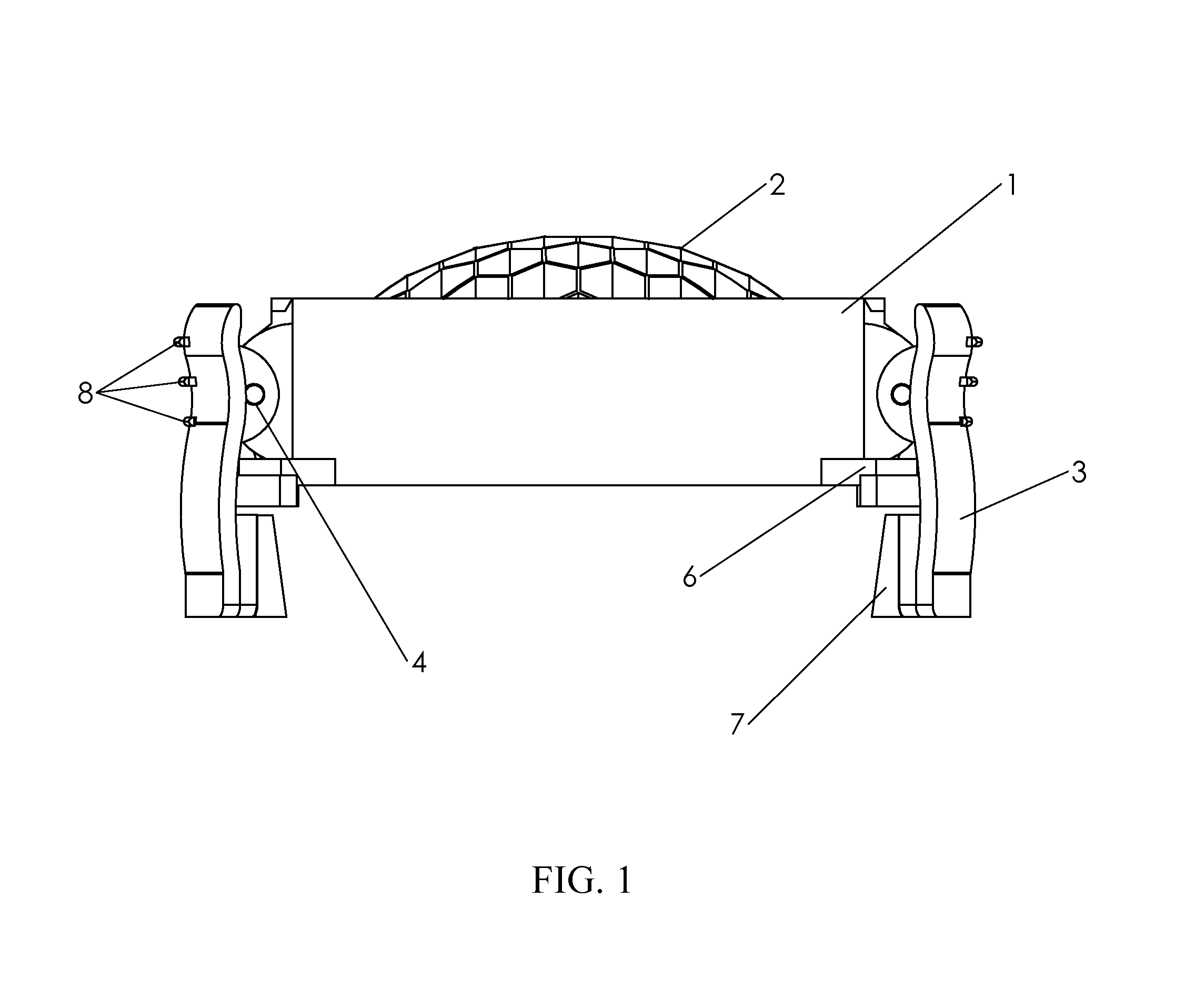
[0039]The invention shows an anti-reflective device in FIG. 1 where the main cylindrical body 1 surrounds thin walled protrusions extending parallel to the optical axis of an optical device 2. Rotatably attached 4 to the main body 1 are the attachment means 3 which allow for the connection of the device to an optical product. Also related in FIG. 1 are structures 6 allowing the placement of the device on an optical product in such a way that ensures that the thin walled protrusions extend parallel to the optical axis of the optical product. Once the device has been placed on an optical product, the elastomeric material 7 that may comprise a portion or all of the attachment members will aid in ensuring a secure fit of the device on an optical product. In order to ease the gripping and placement of the device onto an optical product, protrusions 8 may be added to the attachment members 3 to allow for a more secure and / or more ergonomic grip of the device.

[0040]In FIG. 2 the same devic...


PUM


Abstract

This invention comprises an anti-reflective device comprised of a main cylindrical body, with thin walled protrusions attached to an optical product via the use of one or more attachment members which clamp to the external body of the aforementioned optical product. The anti-reflective device is to be used on optical products such as binoculars, monocular, rifle scopes, and spotting scopes, to prevent the return to an object of visible reflections of light emitted from the surface of the objective lens of an optical product. In a simple one-handed motion, the anti-reflective device is to be clamped to the external body of an optical product, used as an anti-reflective device, and removed via a simple one-handed motion.

Description


Claims


Application Information

Patent Timeline
Owner CARSON OPTICAL
Why Eureka
Eureka Blog
Learn More