
Flush lock for casement window

Active Publication Date: 2014-03-13
INTERLOCK USA
View PDF51 Cites 15 Cited by
  • Summary
  • Abstract
  • Description
  • Claims
  • Application Information

AI Technical Summary

Benefits of technology

The present invention provides a casement window lock that allows for complete reversal of the handle from the locking position to the unlocking position and vice versa. Additionally, it prevents back driving the locking mechanism.

Problems solved by technology

The most relevant prior art does not teach or disclose a locking mechanism capable of low profile (on the order of 8 mm) flush mounting that can be adapted to work with existing tie bar locking designs.
This prior art does not disclose, describe, or suggest any type of lifter mechanism in combination with the fork component to achieve a significantly reduced profile lock actuation.
Nor does this prior art design introduce additional linkage to prevent back driving the lock.

Method used


Image

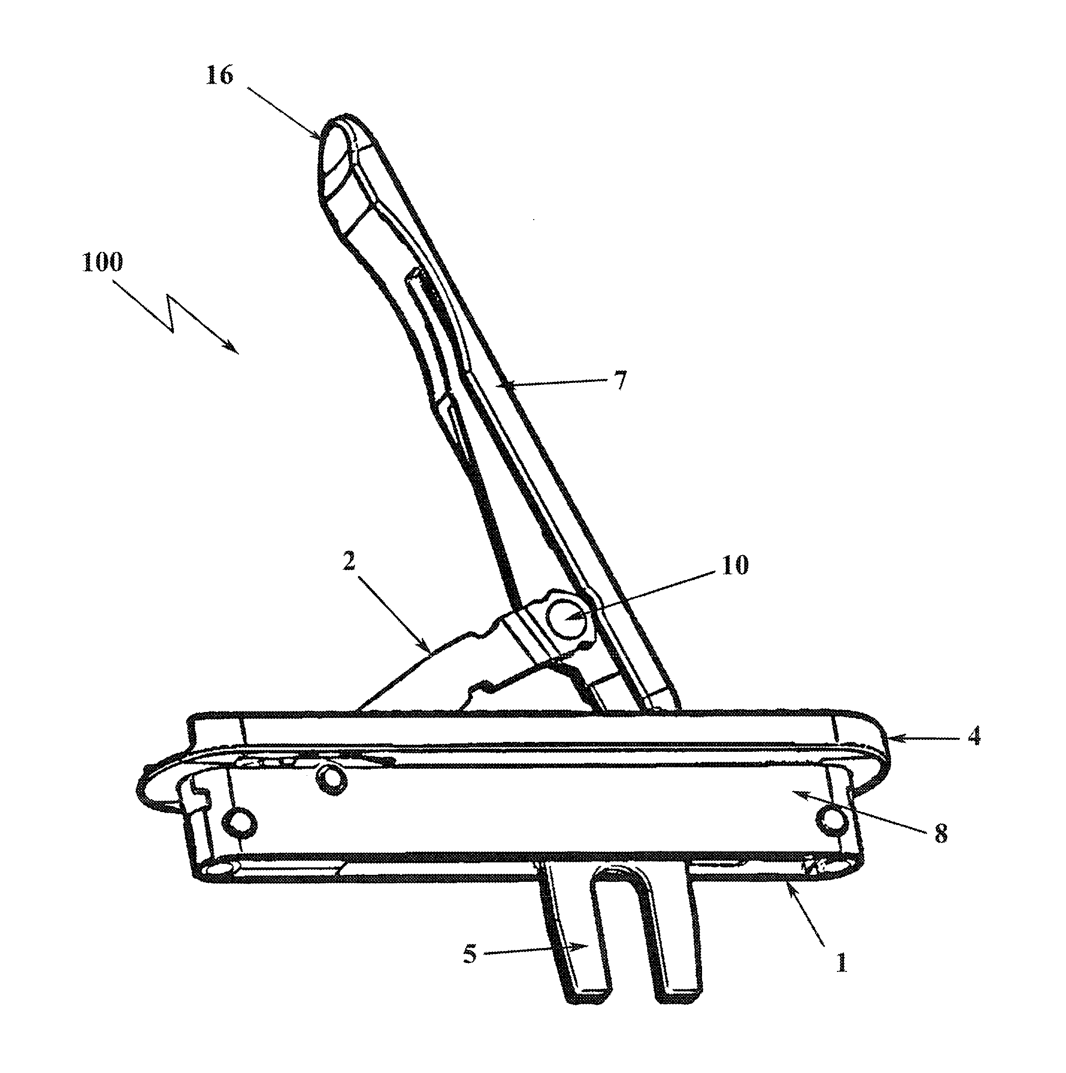
  • Flush lock for casement window
  • Flush lock for casement window
  • Flush lock for casement window

Examples


Embodiment Construction

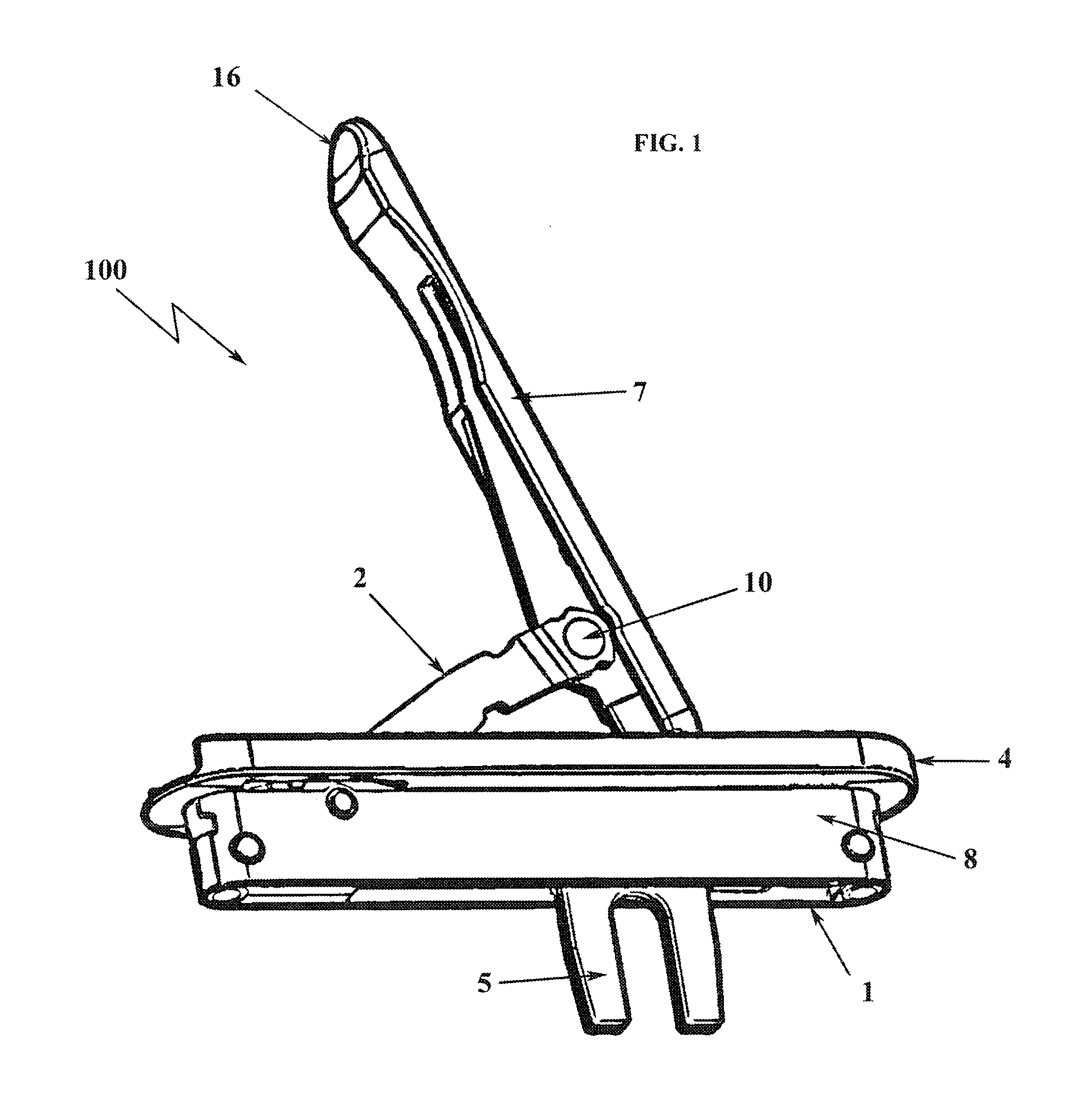
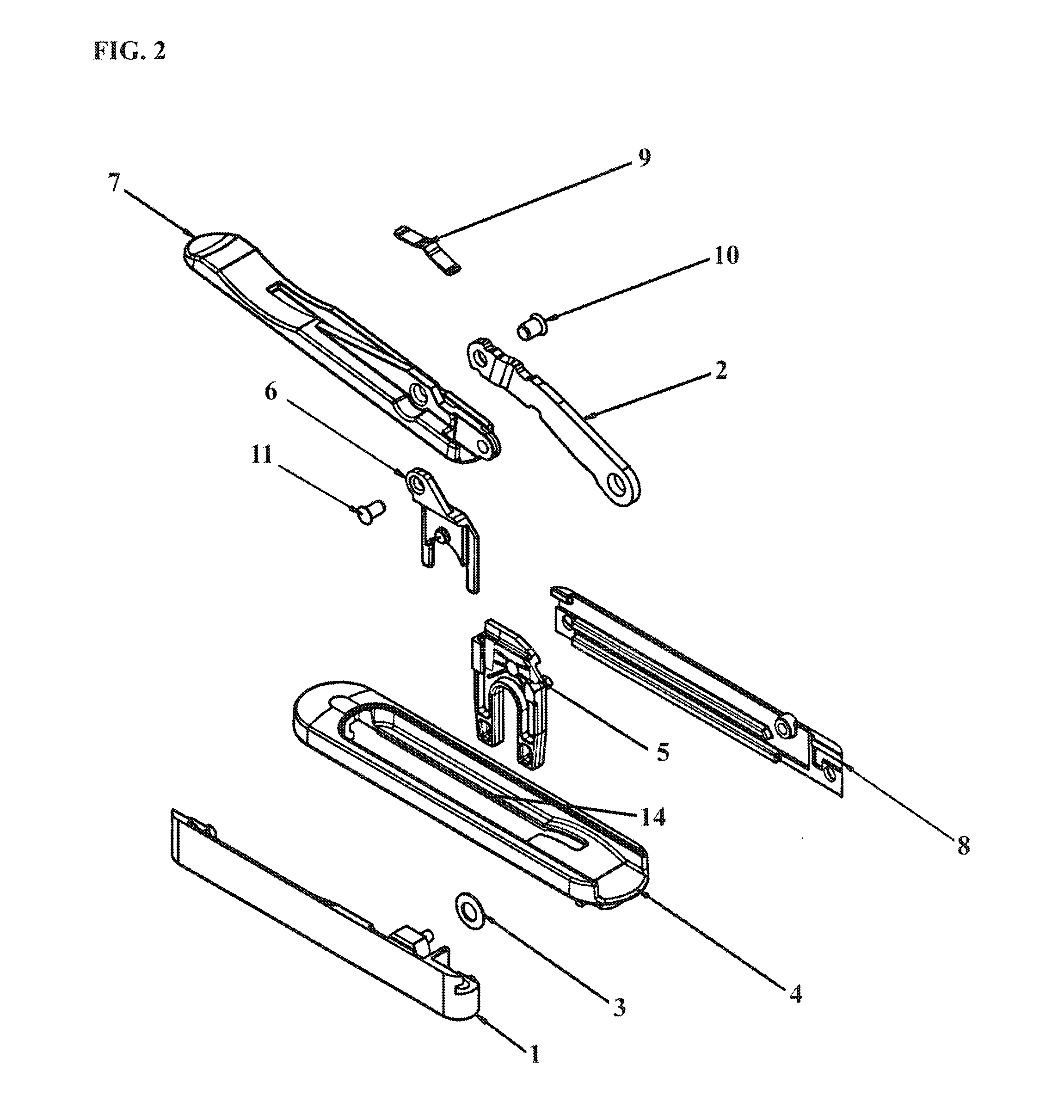
[0050]In describing the preferred embodiment of the present invention, reference will be made herein to FIGS. 1-19 of the drawings in which like numerals refer to like features of the invention.

[0051]The lock of the present invention is a low profile, flush design, that protrudes from the window frame significantly less than the prior art, at about 8 mm compared to 25 mm in the current prior art designs. When locking a casement window, the window is closed generally by a crank. The strikes on the moving sash are brought close to the pins on a tie bar mounted to the non-moving window frame. The lock handle is then thrown. This drives a fork component within the lock, which engages the tie bar and drives it, moving the tie bar pins into engagement with corresponding hooks or strikes. The fork component is preferably a flat structure adapted to slide within the lock casing, preferably having two extensions, such as leg portions, for engaging a tie bar. The strikes generally have a ramp...


PUM


Abstract

A low profile actuating window lock for casement windows having a handle actuate a lifter that slides vertically on a fork component in slidable communication with the window lock casing, the handle pivotable about the lifter and pivotable about a restrictor arm that pivots relative to the casing, allowing the handle to rotate fully from the locked position to the unlocked position with low clearance from the window frame. The pivot points of the handle, lifter, restrictor arm configuration allow for an over center linkage that prevents back driving the casement window lock.

Description

BACKGROUND OF THE INVENTION[0001]1. Field of the Invention[0002]The present invention is directed towards window locks, and particularly toward manual handles for actuating window locks. Specifically, the present invention is directed to a flush mount or low profile actuating window lock for casement windows. More specifically, the present invention is directed to a flush mounted lock actuator designed to drive a lock bar that locks and unlocks a casement window, and protrudes from the window frame significantly less than prior art designs while employing linkage to prevent the actuator from being back driven from either the locked position or unlocked position. The present invention introduces a lifter and a restrictor arm that shift the pivot points of the handle. The lifter moves vertically relative to a horizontally driving fork component helping to achieve a low profile actuation of the lock.[0003]2. Description of Related Art[0004]Generally, a casement window is a window unit ...

Claims


Application Information

Patent Timeline
IPC IPC(8): E05C19/10
CPCE05C19/10E05C9/10E05B5/00Y10T292/0951E05B5/006E05B15/0006
Inventor MINTER, PETER J.RUSPIL, MATHEW D.
Owner INTERLOCK USA
Learn More