Adjustable wrench

a wrench and adjustment technology, applied in the field of wrenches, can solve the problems of troublesome use, difficult to know the size of the required opening, and complicated operation, and achieve the effects of stable action force, smooth operation, and quick adjustmen

Active Publication Date: 2014-03-13
CHANG HSUEH O HSU
View PDF17 Cites 9 Cited by
  • Summary
  • Abstract
  • Description
  • Claims
  • Application Information

AI Technical Summary

Benefits of technology

The present invention is a tool for adjusting the size of a space, such as a space between the jaws of a screw or nut. The tool has a fixed jaw base and an adjustable jaw base that can be moved relative to the fixed jaw base. The fixed jaw base has a curved first operation portion located between one side of the end surface and the pivot portion, and the adjustable jaw base has a protruding second operation portion that corresponds to the first operation portion. Both the first and second operation portions can adjust the space. The tool also has a poke rod that applies an axial force to a slide rod to push it and ensure effective retraction of the spring. The tool can be conveniently used in either clockwise or counterclockwise rotation of the workpiece. The space between the jaws is defined and can hold a hexagonal screw or nut in place during turning. The tool provides improved stability and stability of the turning process.

Problems solved by technology

In fact, it is difficult to know the size of the required opening.
This is quite troublesome when in use.
Besides, when the wrench is operated at an angle which is hard to turn the workpiece or there is an obstacle during the operation, the user has to adjust the wrench at a proper angel to turn the workpiece.
The entire operation is complicated and the work efficiency is low.
It is inconvenient for use.
It is not beneficial to adjust a desired opening with one handle.
When the opening is enlarged by the angled portion of the nut, the opening cannot automatically restore to the required size for turning the workpiece.
This is not beneficial to turn the workpiece continuously.
After a period of time, the slide may be jammed to influence its normal function.

Method used


Image

  • Adjustable wrench
  • Adjustable wrench
  • Adjustable wrench

Examples


Embodiment Construction

[0033]Embodiments of the present invention will now be described, by way of example only, with reference to the accompanying drawings.

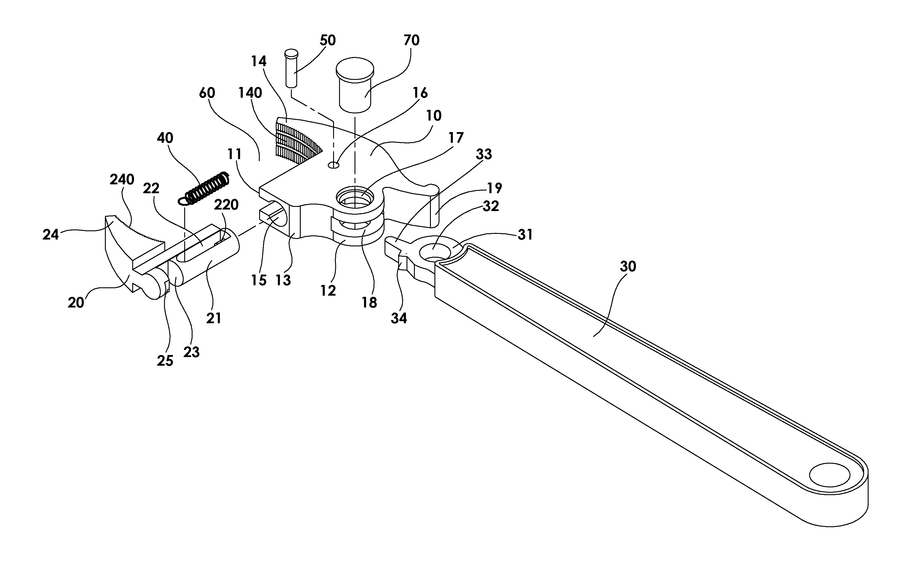
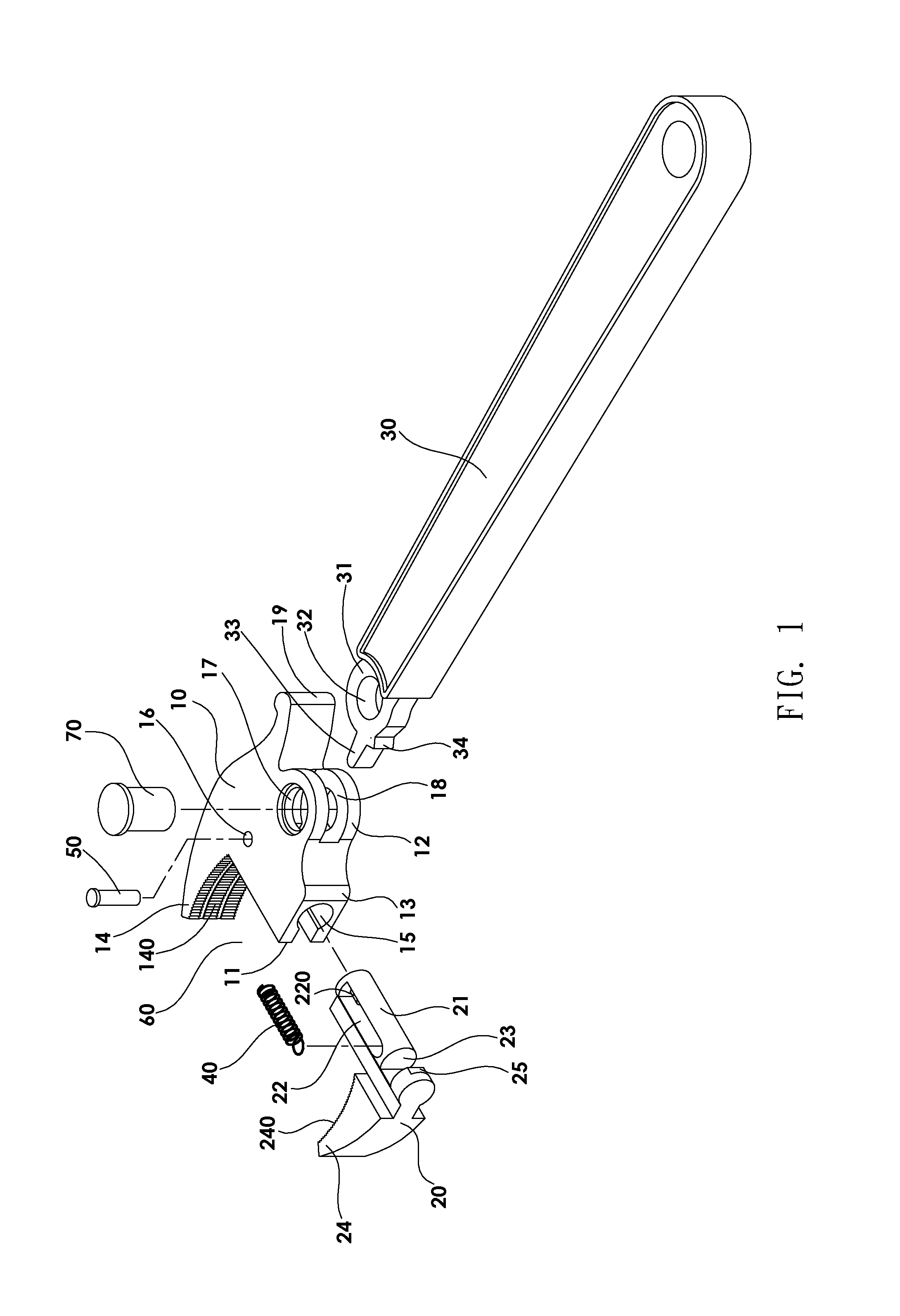
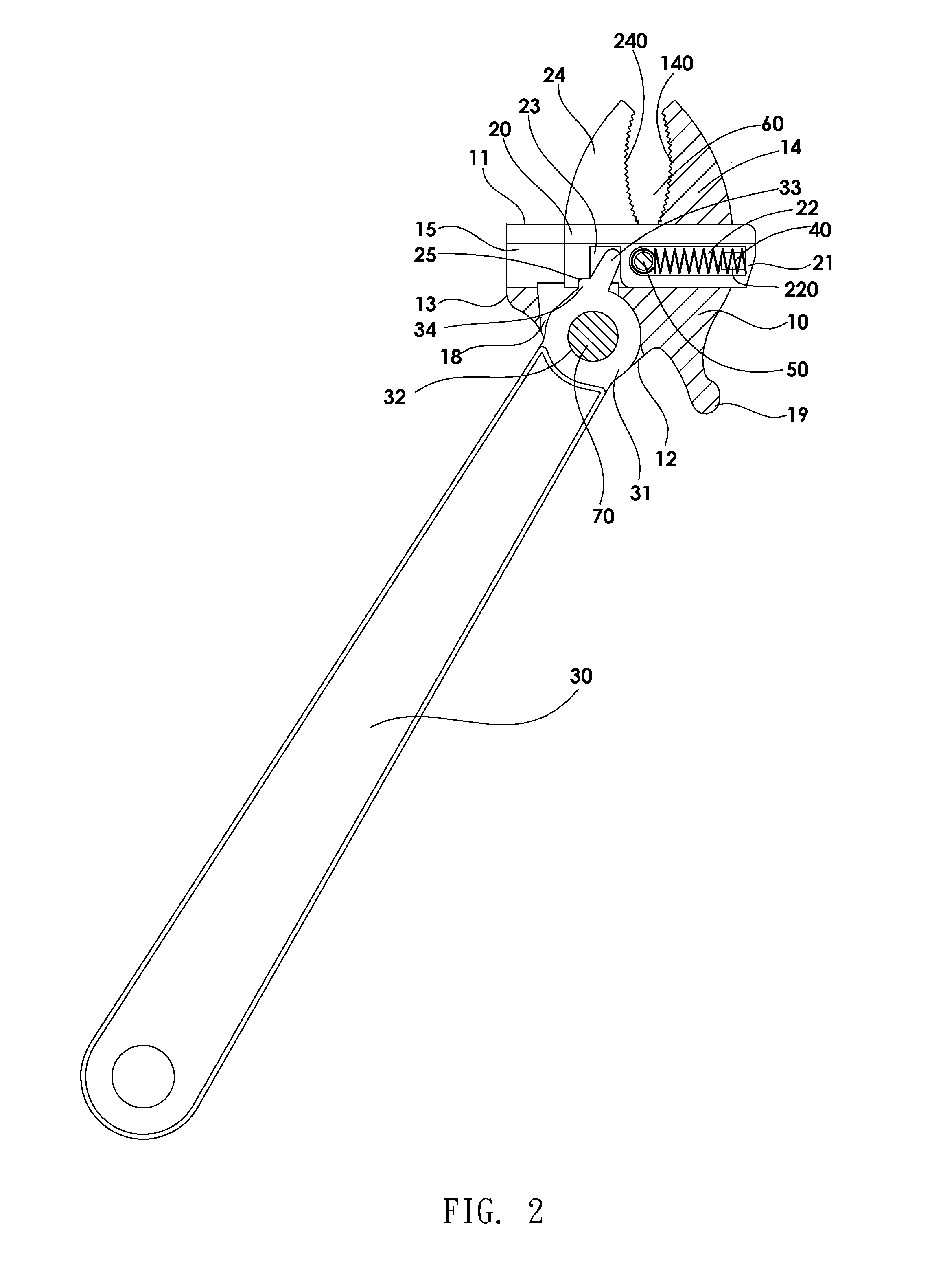
[0034]As shown in FIG. 1 and FIG. 2, the adjustable wrench according to a preferred embodiment of the present invention comprises a fixed jaw base 10, an adjustable jaw base 20, and a handle 30. The fixed jaw base 10 comprises an end surface 11 at a front end thereof, a pivot portion 12 at a rear end thereof, a curved first operation portion 13 between one side of the end surface 11 and the pivot portion 12, a first jaw 14 extending forward from another side of the end surface 11, a slide groove 15 formed in the front end of the fixed jaw base 10 and parallel to the end surface 11, a pin hole 16 extending through the fixed jaw base 10 and perpendicular to the slide groove 15, a pivot through hole 17 at the pivot portion 12, and a trough 18 in the pivot portion 12 to communicate with the slide groove 15. The adjustable jaw base 20 comprises a slide rod...


PUM


Abstract

An adjustable wrench includes a fixed jaw base, an adjustable jaw base and a handle. The adjustable jaw base includes a slide rod which is slidably movable in a slide grove of the fixed jaw base to adjust the space to clip an object. A poke rod of the handle is located in a poke recess of the slide rod to provide an action force or a limit force to the slide rod. The slide rod is provided with a spring to react to the action force or limit force of the poke rod. One side of the fixed jaw base has a first operation portion for the user to press and control the space to clip the object, enhancing the convenience to turn a workpiece. Particularly, when the handle is pivoted, the poke rod in the poke recess will direct act on the center of the slide rod.

Description

BACKGROUND OF THE INVENTION[0001]1. Field of the Invention[0002]The present invention relates to a wrench, and more particularly to, an adjustable wrench which can turn a workpiece conveniently and smoothly.[0003]2. Description of Related Art[0004]An adjustable wrench is used to turn a pipe member, a screw or a nut. The adjustable wrench comprises a screw member to move an adjustable jaw so that the opening between the adjustable jaw and the fixed jaw can be adjusted to clip a workpiece. In fact, it is difficult to know the size of the required opening. The screw member needs to be adjusted many times to fit on the workpiece. This is quite troublesome when in use. Besides, when the wrench is operated at an angle which is hard to turn the workpiece or there is an obstacle during the operation, the user has to adjust the wrench at a proper angel to turn the workpiece. The entire operation is complicated and the work efficiency is low.[0005]Taiwan Patent Publication No. 136716 disclose...

Claims


Application Information

Patent Timeline
IPC IPC(8): B25B13/20
CPCB25B13/12
Inventor CHANG, HSUEH-O HSU
Owner CHANG HSUEH O HSU
Why Eureka
Try Eureka