
Methods and Devices to Control Fluid Volumes, Reagent and Particle Concentration in Arrays of Microfluidic Drops

a microfluidic drop and array technology, applied in the field of microfluidics, can solve the problems of arraying fluid volumes, unable to isolate and study individual cells, and amenable to further reduction of fluid volumes, so as to achieve small hydrodynamic resistance, small hydrodynamic resistance, and small hydrodynamic resistance

Active Publication Date: 2014-02-20
TEXAS TECH UNIV SYST
View PDF1 Cites 24 Cited by
  • Summary
  • Abstract
  • Description
  • Claims
  • Application Information

AI Technical Summary

Benefits of technology

The present invention is a microfluidic device that includes one or more parking loops connected to a main conduit. The parking loops have a smaller hydrodynamic resistance than the lower branch with a fluidic trap, which allows for the separation of drops, cells, or compositions based on their size. The device can also have an array of parking loops, which provides for serial dilution of the drops, cells, or compositions in the solution. The device can be used to transport drops, cells, or compositions and form a droplet-based concentration gradient in solution. The technical effects of the invention include improved separation and concentration of drops, cells, or compositions, as well as improved control over the movement and concentration of the sample solution.

Problems solved by technology

Current industry approaches for arraying fluid volumes involve expensive methods such as robotic dispensing in micro-scale multi-well plates or spotting of fluids on substrates.
These approaches suffer from using microliter-scale fluid volumes, and are also not amenable to further reduction in fluid volumes due to liquid evaporation.
Moreover, these approaches do not allow isolation and study of individual cells, which is important in applications such as cancer and bacterial infections, where there is a need to identify the ‘rogue’ cells among a population.

Method used


Image

  • Methods and Devices to Control Fluid Volumes, Reagent and Particle Concentration in Arrays of Microfluidic Drops
  • Methods and Devices to Control Fluid Volumes, Reagent and Particle Concentration in Arrays of Microfluidic Drops
  • Methods and Devices to Control Fluid Volumes, Reagent and Particle Concentration in Arrays of Microfluidic Drops

Examples


Embodiment Construction

[0039]While the making and using of various embodiments of the present invention are discussed in detail below, it should be appreciated that the present invention provides many applicable inventive concepts that can be embodied in a wide variety of specific contexts. The specific embodiments discussed herein are merely illustrative of specific ways to make and use the invention and do not delimit the scope of the invention.

[0040]To facilitate the understanding of this invention, a number of terms are defined below. Terms defined herein have meanings as commonly understood by a person of ordinary skill in the areas relevant to the present invention. Terms such as “a”, “an” and “the” are not intended to refer to only a singular entity, but include the general class of which a specific example may be used for illustration. The terminology herein is used to describe specific embodiments of the invention, but their usage does not delimit the invention, except as outlined in the claims.

[...


PUM

PropertyMeasurementUnit
volumeaaaaaaaaaa
volumeaaaaaaaaaa
volumeaaaaaaaaaa

Abstract

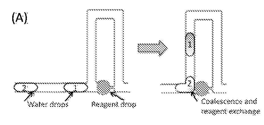
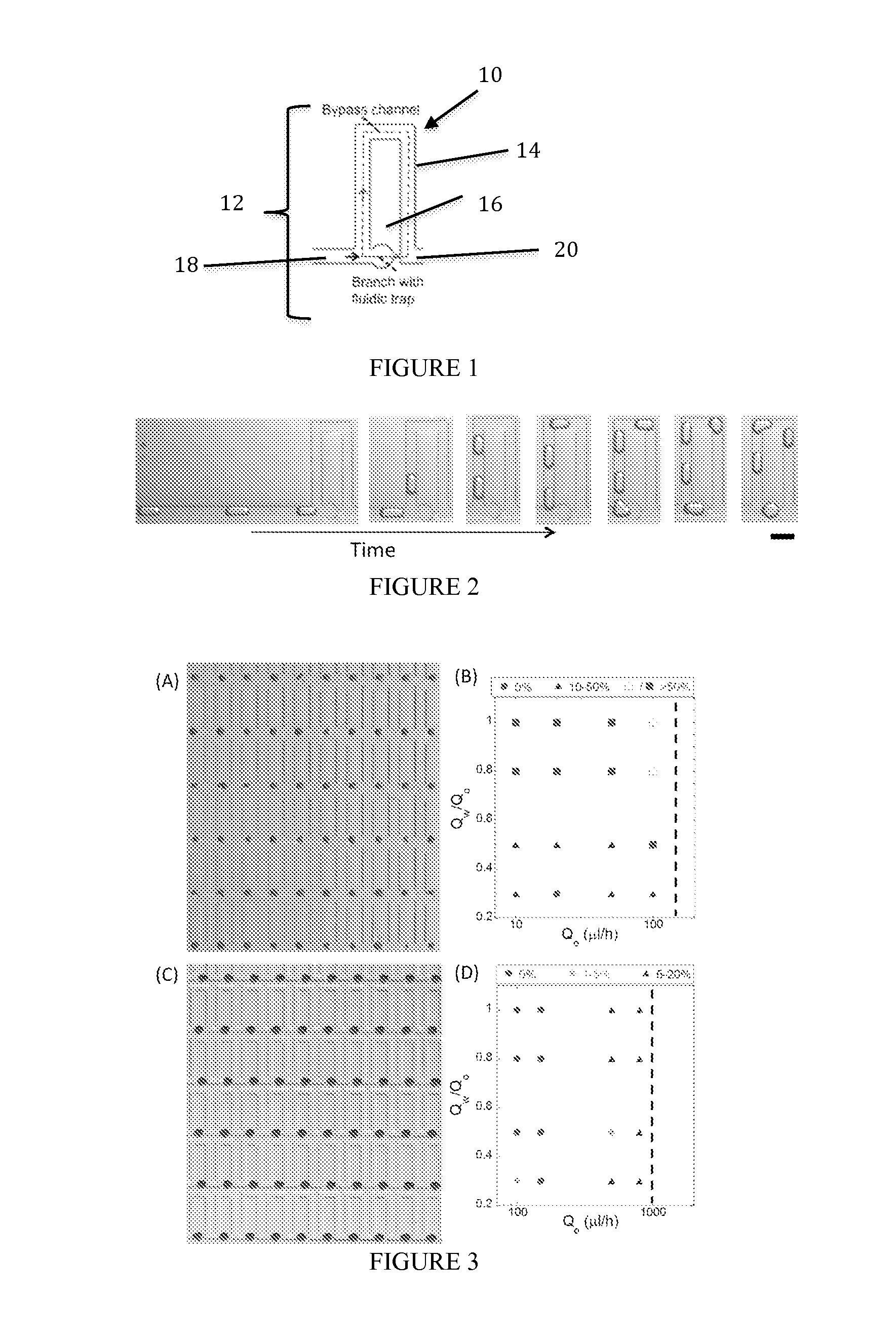
The present invention includes a microfluidic device comprising one or more parking loops 12, each parking loop 12 comprising a bypass channel 14 and a lower branch 16 capable of retaining one or more drops, wherein bypass channel 14 has a smaller hydrodynamic resistance than the lower branch 16.

Description

TECHNICAL FIELD OF THE INVENTION[0001]The present invention relates in general to the field of microfluidics, and more particularly, to methods and devices to control fluid volumes, reagent concentration, and particle concentration in arrays of microfluidic drops.BACKGROUND ART[0002]Without limiting the scope of the invention, its background is described in connection with microfluidic structures. Current industry approaches for arraying fluid volumes involve expensive methods such as robotic dispensing in micro-scale multi-well plates or spotting of fluids on substrates. These approaches suffer from using microliter-scale fluid volumes, and are also not amenable to further reduction in fluid volumes due to liquid evaporation. Moreover, these approaches do not allow isolation and study of individual cells, which is important in applications such as cancer and bacterial infections, where there is a need to identify the ‘rogue’ cells among a population.[0003]Droplet-based microfluidic...

Claims


Application Information

Patent Timeline
Patent Type & Authority Applications(United States)
IPC IPC(8): C12M1/00
CPCC12M47/02B01L3/502784B01L2200/0668B01L2200/0673B01L2300/088B01L2400/0487G01N35/1002G01N2035/1034Y10T29/49
Inventor VANAPALLI, SIVA A.BITHI, SWASTIKA S.SUN, MENG
Owner TEXAS TECH UNIV SYST
Learn More