
Riser for Coil Tubing/Wire Line Injection

a coil tubing/wire line and riser technology, which is applied in the direction of special purpose vessels, vessel construction, borehole/well accessories, etc., can solve the problems of high cost and high day rate of coil tubing/wire line work-over procedures, and achieve the effect of reducing the cost of the procedure and avoiding the cost of the day ra

Inactive Publication Date: 2014-02-20
MY TECH L LC
View PDF3 Cites 4 Cited by
  • Summary
  • Abstract
  • Description
  • Claims
  • Application Information

AI Technical Summary

Benefits of technology

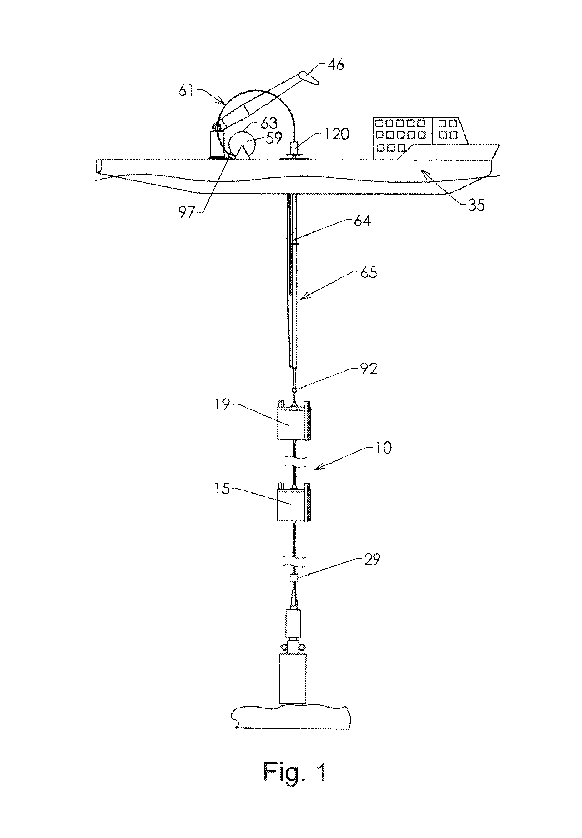
[0005]The present invention is directed to a system including a self supporting riser (SSR) which is connected to a well to provide fluid communication to fossil hydrocarbon reservoirs deep below the seafloor. The SSR is constructed of a plurality of joints comprising regular joints and specialty joints that define the SSR and are selected to optimize the SSR for a well in a specific location. A unique aspect of the invention is further directed to a small vessel subject to high vessel motions that permits a coil tubing / wire line system to be mounted on a stabilizer system mounted on the vessel.

Problems solved by technology

These vessels cost millions of dollars and have day rates that frequently can not be cost justified to perform work-over coil tubing / wire line procedures.

Method used


Image

  • Riser for Coil Tubing/Wire Line Injection
  • Riser for Coil Tubing/Wire Line Injection
  • Riser for Coil Tubing/Wire Line Injection

Examples


Embodiment Construction

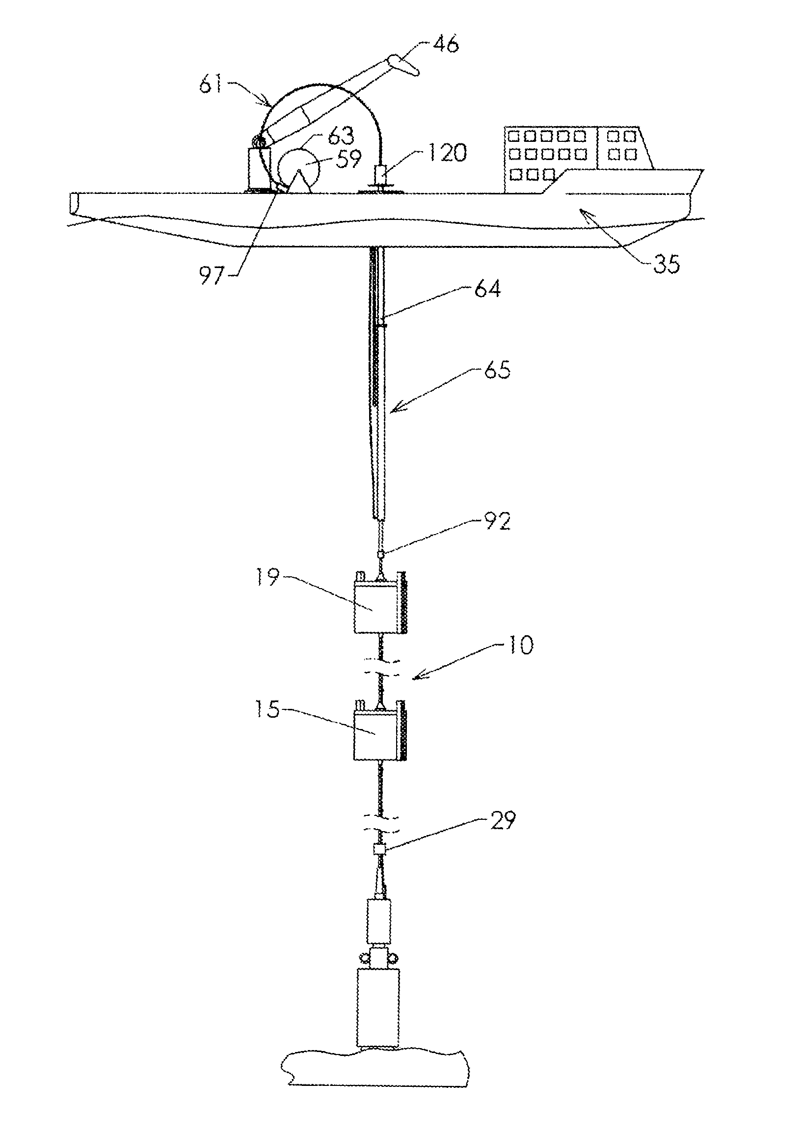
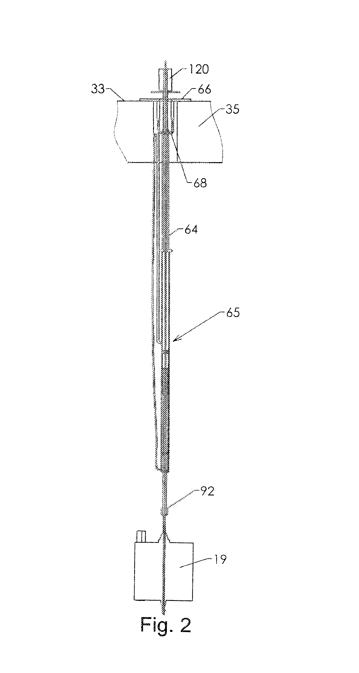
[0011]Referring to FIG. 1, reference is made to Ser. No. 12 / 714,919 and the drawing therein for a more detail description, a novel Riser Vessel Interface System (RVI) 60 facilitates using the SSR for downhole intervention and workover through the SSR 10 using relatively small vessels. The nature of an SSR is such that it may be relatively sensitive to the magnitude of externally applied tension and to variations in externally applied tension. It is the nature of small vessels that their motions in response to waves and swells are greater than those of larger vessels and substantially greater than the motions of platforms or floating production facilities. The interface between an SSR and a small vessel therefore requires a greater range of motion and less tension variation than is provided by the previous art. The coiled tubing injector must be supported by the vessel, and the weight of deployed tubing normally hangs from the injector.

[0012]Referring to FIG. 1, intervention vessel 3...


PUM


Abstract

The present invention is directed to a system including a self supporting riser (SSR) which is connected to a well to provide fluid communication to fossil hydrocarbon reservoirs deep below the seafloor. The SSR is constructed of a plurality of joints comprising regular joints and specialty joints that define the SSR and are selected to optimize the SSR for a well in a specific location. A unique aspect of the invention is further directed to a small vessel subject to high vessel motions that permits a coil tubing / wire line system to be mounted on a stabilizer system mounted on the vessel. The riser extension that connects the vessel to the self supporting riser preferably has a telescopic joint / section that is designed for the heave of the vessel.

Description

CROSS REFERENCE TO RELATED APPLICATION[0001]This application is a continuation-in-part Application of Ser. No. 12 / 714,919 filed Mar. 1, 2010, entitled “Riser Technology”, which is incorporated herein by reference.STATEMENT REGARDING FEDERALLY SPONSORED RESEARCH OR DEVELOPMENT[0002]Not applicable.FIELD OF INVENTION[0003]The present invention is directed to the interfacing of a Self Supporting Riser (SSR) to a vessel subject to high vessel motions of pitch and roll. The small vessel employs a unique stabilization system for supporting a coil tubing / wire line injector and supporting equipment on the vessel.BACKGROUND OF THE INVENTION[0004]It has been the practice for the intervention in deep wells that recover hydrocarbons from fossil hydrocarbon reservoirs deep below the Gulf of Mexico and other offshore areas to use very large vessels of various designs upon which the equipment for intervention into the wells are supported. These vessels cost millions of dollars and have day rates th...

Claims


Application Information

Patent Timeline
Patent Type & Authority Applications(United States)
IPC IPC(8): E21B19/00B63B39/03
CPCB63B39/03E21B19/002B63B17/00B63B2003/147B63B2017/0072B66C13/02E21B19/004E21B19/006E21B19/22
Inventor YEMINGTON, CHARLES R.
Owner MY TECH L LC
Learn More