Blade cascade with side wall contours and continuous-flow machine

a continuous-flow machine and cascade technology, applied in the direction of liquid fuel engines, marine propulsion, vessel construction, etc., can solve the problems of pressure loss and leave quite a bit of room for improvement, and achieve the effect of reducing secondary flow and improving efficiency

Active Publication Date: 2014-02-06
MTU AERO ENGINES GMBH
View PDF4 Cites 8 Cited by
  • Summary
  • Abstract
  • Description
  • Claims
  • Application Information

AI Technical Summary

Benefits of technology

[0005]It is an object of the present invention to provide a blade cascade for a continuous-flow machine with a reduced secondary flow. Moreover, it is an objective of the invention to create a continuous-flow machine that displays improved efficiency.

Problems solved by technology

Among other things, this leads to pressure losses.
This prior-art side wall contour leads to a reduction of the secondary flows, but this still leaves quite a bit of room for improvement.

Method used


Image

  • Blade cascade with side wall contours and continuous-flow machine
  • Blade cascade with side wall contours and continuous-flow machine

Examples


Embodiment Construction

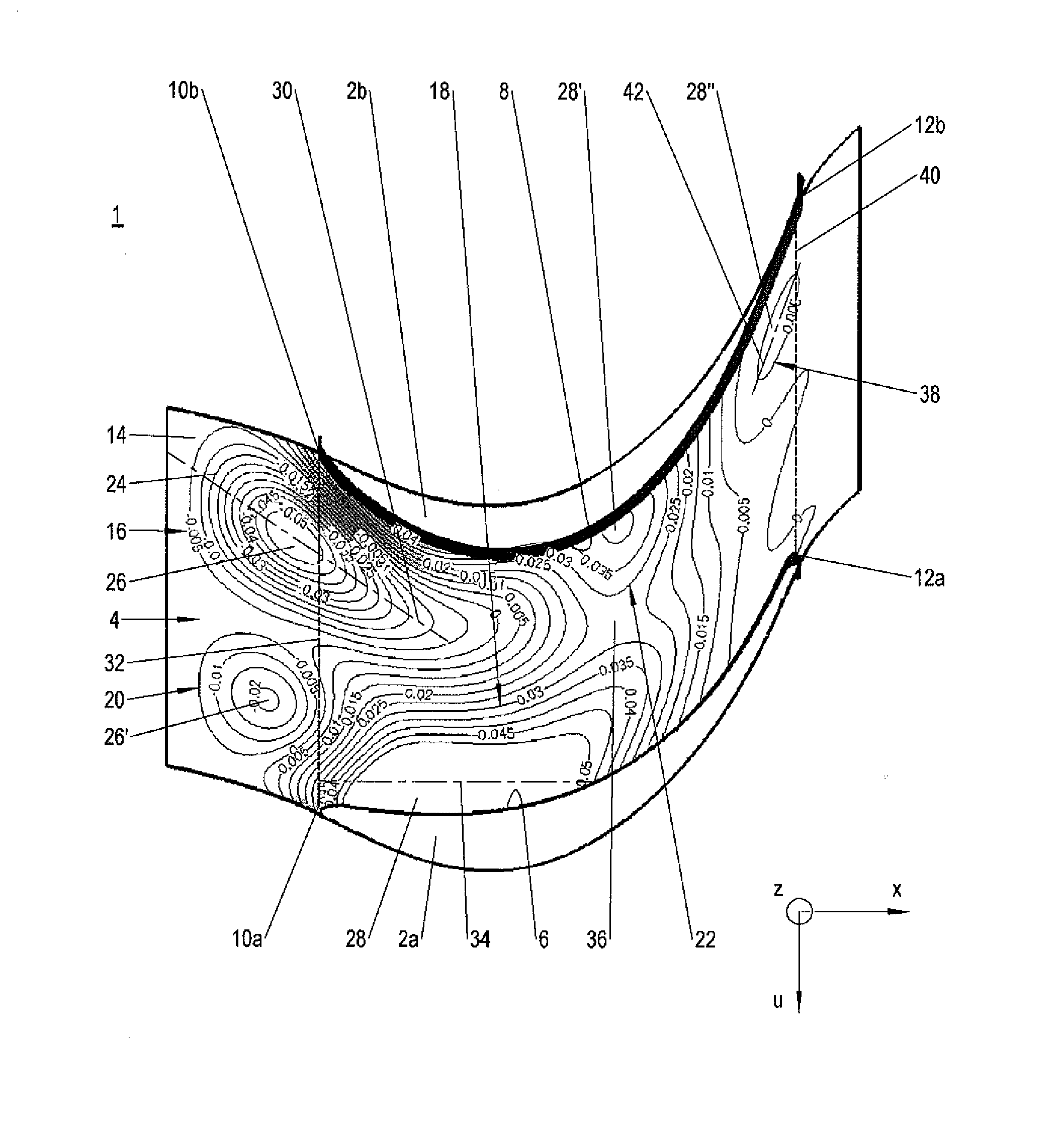
[0024]Below, a preferred embodiment of the invention will be explained in greater detail with reference to a schematic depiction. The single FIG. 1 shows a top view of a developed blade cascade according to the invention in the area of a blade channel.

[0025]As shown in the single FIG. 1, a blade cascade 1 according to the invention shown by way of an example has a plurality of blades 2a, 2b, which are arranged next to each other in the circumferential direction u and which each delimit a blade channel 4. The blade cascade 1 is preferably a blade cascade of an axial continuous-flow machine such as an aircraft engine or a stationary gas turbine. For example, the blade cascade is arranged in the low-pressure turbine of the continuous-flow machine 100, shown schematically for example in FIG. 2. However, the invention is also used in blade cascades for compressors having an axial design or for compressors as well as turbines having a radial and diagonal design.

[0026]A main flow flows thr...


PUM


Abstract

A blade cascade for a continuous-flow machine having a non-axisymmetrical side wall contour, whereby the side wall contour has at least one suction-side depression that, in the circumferential direction, is at a distance from a suction-side wall, and having a section located upstream from the leading edges and a section located downstream from the leading edges, it has a pressure-side elevation that makes a transition to a pressure-side wall and that is located in a front blade area, and it has a pressure-side depression that is located upstream from the pressure-side elevation, and also discloses a continuous-flow machine having such a blade cascade.

Description

[0001]This claims the benefit of European Patent Application EP 12179045.5-1267, filed Aug. 2, 2012 and hereby incorporated by reference herein.[0002]The invention relates to a blade cascade for a continuous-flow machine, and it also relates to a continuous-flow machine.[0003]A fluid flow conveyed through a flow channel is deflected parallel to the side wall by means of a lateral pressure gradient. Since flow layers that are close to the wall—owing to their lower velocity—are deflected more markedly than flow layers that are far away from the wall, a secondary flow is formed that is superimposed over a main flow. Among other things, this leads to pressure losses. The secondary flows occur regularly in blade cascades of continuous-flow machines such as gas and steam turbines. The blade cascades consist of a plurality of vanes or blades which are arranged next to each other in the circumferential direction in a rotation-symmetrical flow channel and between each of which a blade channe...

Claims


Application Information

Patent Timeline
Patent Type & Authority Applications(United States)
IPC IPC(8): F01D5/12
CPCF01D5/12F01D5/143F01D5/145Y02T50/60
Inventor ENGEL, KARL
Owner MTU AERO ENGINES GMBH
Why Eureka
Try Eureka