
Photonically Enabled RF Transmitter/Receiver

a technology of rf transmitter and receiver, applied in the field of radio frequency (rf) transmission and/or reception technology, can solve the problems of low sensitivity of digital simulations associated with such testing, high cost of testing systems designed to employ rf technology to obtain desired detection and/or ranging information,

Active Publication Date: 2014-01-23
THE JOHN HOPKINS UNIV SCHOOL OF MEDICINE
View PDF5 Cites 20 Cited by
  • Summary
  • Abstract
  • Description
  • Claims
  • Application Information

AI Technical Summary

Benefits of technology

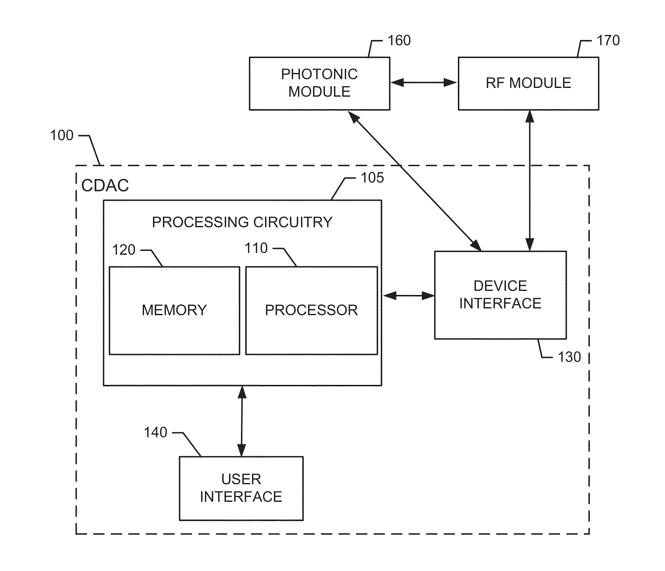
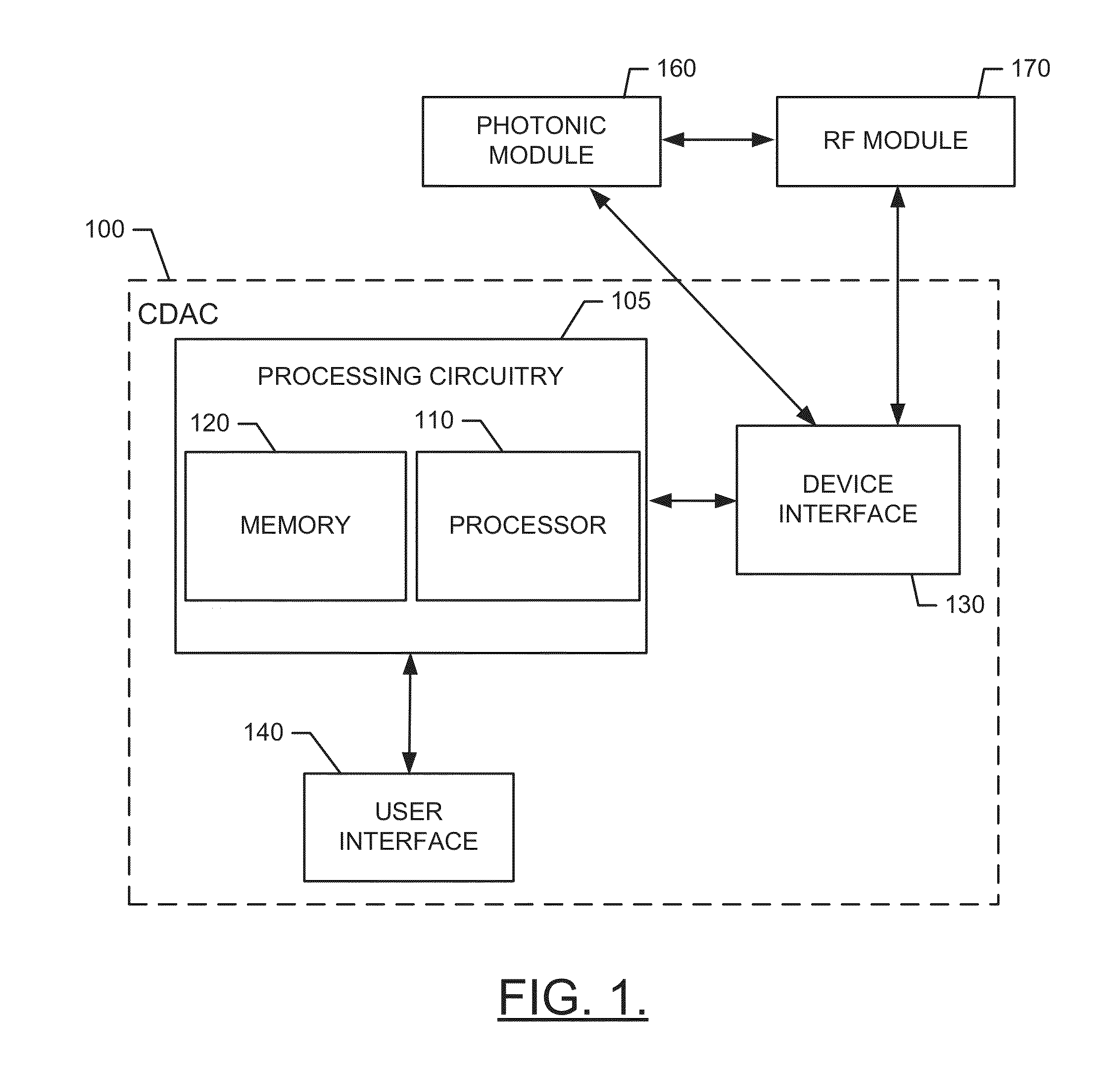
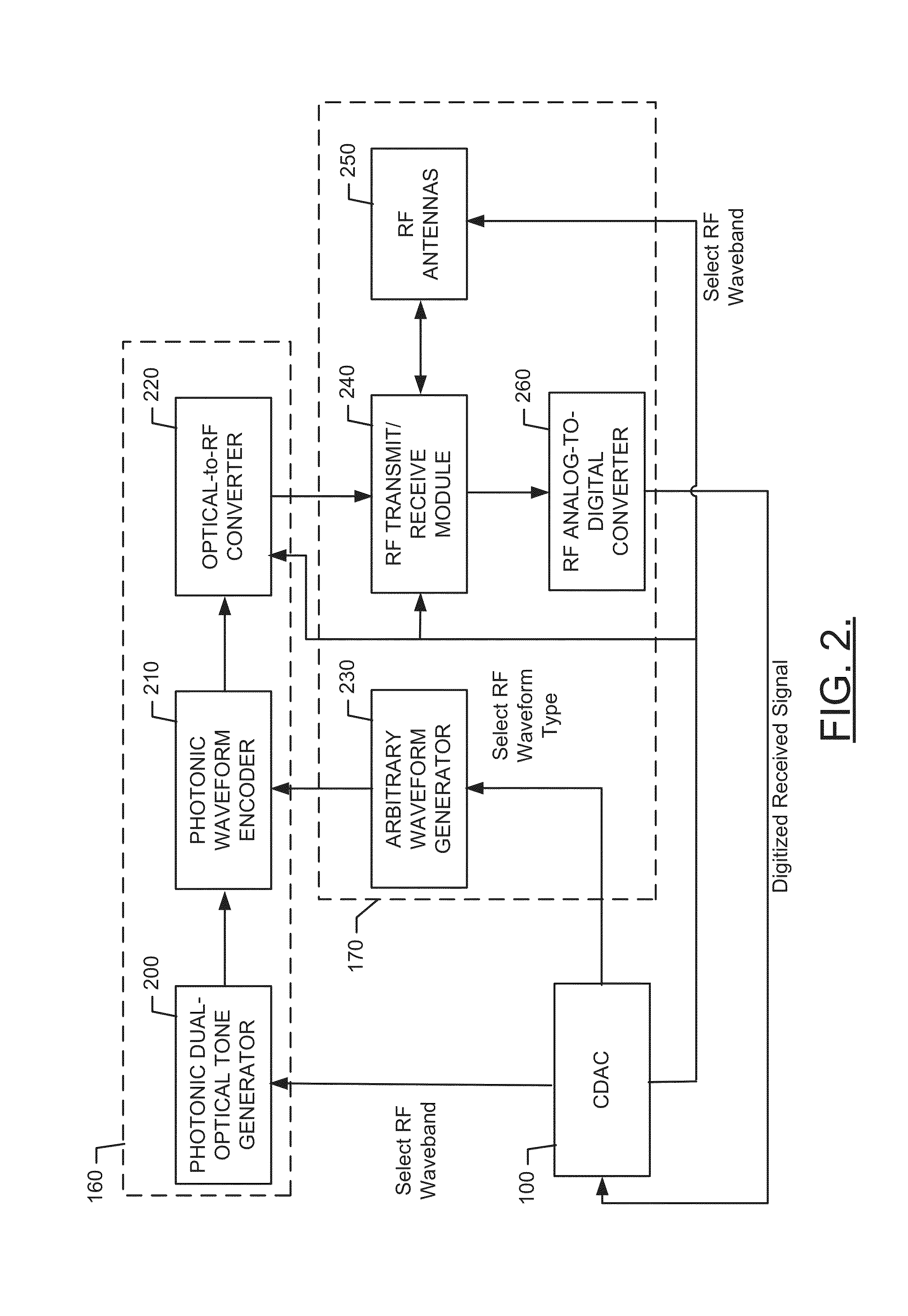
This patent describes a system that allows for accurate range measurements and other information to be gathered in a flexible and capable way. The system can support very wide ranges of carrier frequencies and can be used in subscale radar testing and in the field. It can also be used as a tunable wideband signal generator or frequency source. The system includes a photonic module, an RF module, and processing circuitry that allows an operator to control the photonic module and RF module at least with respect to determining the carrier frequency of the optical tone and the modulation technique to be employed. The detection system can generate an optical tone for modulation and convert it to RF domain after modulation.

Problems solved by technology

Testing of systems that are designed to employ RF technology to obtain desired detection and / or ranging information can be expensive, and the digital simulations associated with such testing can often lack realism.

Method used


Image

  • Photonically Enabled RF Transmitter/Receiver
  • Photonically Enabled RF Transmitter/Receiver
  • Photonically Enabled RF Transmitter/Receiver

Examples


Embodiment Construction

[0014]Some example embodiments now will be described more fully hereinafter with reference to the accompanying drawings, in which some, but not all example embodiments are shown. Indeed, the examples described and pictured herein should not be construed as being limiting as to the scope, applicability or configuration of the present disclosure. Rather, these example embodiments are provided so that this disclosure will satisfy applicable legal requirements. Like reference numerals refer to like elements throughout.

[0015]A cost-effective and flexible way to generate radar data using subscale targets would be of great interest in the defense community. Using subscale targets and employing Maxwell's equations, radar effects may be held constant while scaling both target size and radar wavelength by the same factor. A millimeter-wave subscale radar can be implemented using photonics technologies, which can easily satisfy the faster pulsing and shorter pulse width requirements of a compa...


PUM


Abstract

A detection system includes a photonic module, a radio frequency (RF) module and processing circuitry. The photonic module may be configured to generate an optical tone for modulation in an optical domain prior to conversion to the RF domain. The RF module may be configured to interface with the photonic module to receive a transmission signal converted from the optical domain. The processing circuitry may be configured to interface with the photonic module and RF module to enable an operator to control of the photonic module and the RF module at least with respect to selectively determining a carrier frequency of the optical tone and a modulation technique to be employed with respect to the transmission signal converted from the optical domain.

Description

CROSS-REFERENCE TO RELATED APPLICATION[0001]This application claims priority to and the benefit of co-pending U.S. Provisional Application No. 61 / 674,473 filed on Jul. 23, 2012, the entire contents of which are hereby incorporated herein by reference.TECHNICAL FIELD[0002]Exemplary embodiments of the present disclosure generally relate to radio frequency (RF) transmission and / or reception technology, and more specifically relate to employment of a photonically enabled RF transmitter and / or receiver.BACKGROUND[0003]Radar is one example of a system that employs RF technology to obtain useful ranging information. However, other useful information (e.g., Doppler and radar cross section) can also be obtained by employing RF technology. Testing of systems that are designed to employ RF technology to obtain desired detection and / or ranging information can be expensive, and the digital simulations associated with such testing can often lack realism. Accordingly, a mechanism by which to gener...

Claims


Application Information

Patent Timeline
Patent Type & Authority Applications(United States)
IPC IPC(8): G01S13/86H04B10/2575G01S13/02
CPCG01S13/86G01S13/02H04B10/2575H04B10/90H04B2210/006
Inventor LOHR, MICHELE B.SOVA, RAYMOND M.DENNIS, MICHAEL L.PAVEK, RICHARD E.FUNK, KEVIN B.
Owner THE JOHN HOPKINS UNIV SCHOOL OF MEDICINE
Learn More