
Powered converter dolly and securing device

a technology of securing device and dolly, which is applied in the direction of transportation and packaging, railway components, wagons/vans, etc., can solve the problems of affecting the safety of personnel, and requiring a great deal of manual effort from the operator to lift the front end of the dolly, so as to avoid excessive physical strain and injury to personnel.

Active Publication Date: 2014-01-16
TWENTY FIRST CENTURY TRANSPORT SYST INC
View PDF10 Cites 23 Cited by
  • Summary
  • Abstract
  • Description
  • Claims
  • Application Information

AI Technical Summary

Benefits of technology

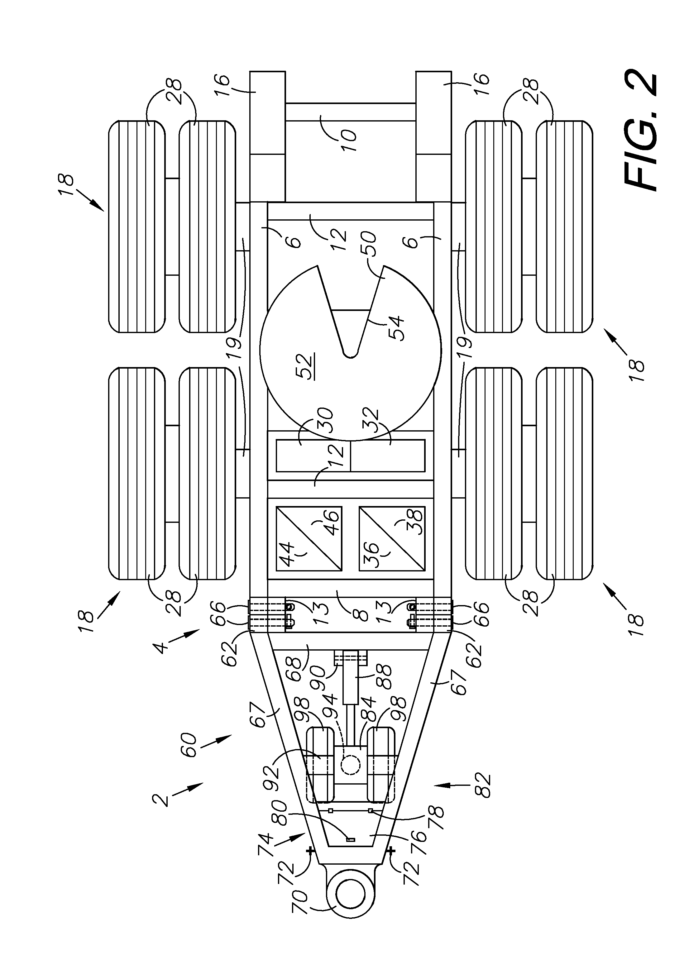
This patent describes a dolly that can be controlled by an operator using a remote control to move the dolly and connect it to a load-trailer or lead trailer safely and easily. The dolly is powered by its own battery and can be easily maneuvered around a trailer yard or connected to a lead trailer without causing physical strain or injury. The landing gear can be adjusted using a hydraulic cylinder to have traction or can have a hydraulic scissor lift to move trailers around a trailer yard without needing to retract the landing gear on the trailer.

Problems solved by technology

The conventional method of assembling trailers and dollies creates dangerous conditions for people maneuvering the dollies and attaching them to a tractor-trailer, and for personnel around backward moving tractor-trailer assemblies.
A great deal of manual effort is required of an operator to lift the front end of the dolly off the ground and keep the dolly under control when maneuvering it around the trailer yard coupling it to a load-trailer, or assisting with coupling the dolly to a lead-trailer.
Problems may be encountered when transporting trailers, and multiple linked dolly and trailer assemblies on railcars, and properly securing them to the railcar due to the securing points on the dollies and trailers being in unpredictable locations.

Method used


Image

  • Powered converter dolly and securing device
  • Powered converter dolly and securing device
  • Powered converter dolly and securing device

Examples


second alternative embodiment

XI. Second Alternative Embodiment Trolley System 1002

[0122]Reference numeral 1002 generally designates a second alternative embodiment trolley system embodying the principles of the disclosed subject matter. Referring to FIGS. 29-32, the trolley system 1002 is shown and described including a trolley 1004 securing an object, such as a tractor 1086 to a railcar 116 using a connector ring 1062. The connector ring 1062 is a circular mushroom-shaped device having a hitch 1064, similar to the hitch 864 described above, depending from the center. A plurality of slots 1066 radiate out from the top of the body 1065 providing an attachment point for the links of a chain 1072 hanging below the frame 1088 of the tractor 1086. A plurality of eyelets 1068 located at the edge of the body 1065 are provided for receiving hooks (not shown) that may be attached to the end of the chains 1072. The connector ring 1062 is mounted by either first attaching the ring 1062 to the chains 1072, or by attaching ...

sixth alternative embodiment

XV. Sixth Alternative Embodiment Trolley System 1402

[0126]Reference numeral 1402 generally designates a sixth alternative embodiment trolley system embodying the principles of the disclosed subject matter. Referring to FIGS. 38-40, the trolley system 1402 is shown and described including a trolley 1404 using a scissor lift 1326 to raise and lower a mini-fifth wheel hitch 1412. The scissor lift 1326 is designed and functions in a similar manner as above, and is used to raise and lower a platform 1420 having a mini fifth wheel hitch 1412 attached. The fifth wheel hitch 1412 has a pickup plate 1414 with a slot 1416 for receiving the kingpin of a trailer. The fifth wheel hitch 1412 is pivotally attached to a base plate 1418. The base plate 1418 is movable along the length of the platform 1420 within an elongated aperture 1422 disposed within the platform 1420. A pivot pin 1424 at the rear of the base plate 1418, and a guide pin 1426 extending from the lever 1428 at the front of the base...

embodiment trolley 1704

XVIII. Ninth Alternative Embodiment Trolley 1704

[0133]Reference numeral 1704 generally designates a ninth alternative embodiment trolley embodying the principles of the disclosed subject matter. Referring to FIGS. 47-49, the trolley 1704 includes trolley frame member 1705 and a fifth wheel plate 1706 connected by a cross-frame 1708 powered by a hydraulic piston 1714. The piston can raise and lower the fifth wheel plate 1706 as necessary to connect with transport shipping containers or other means. A fifth-wheel bracket 1710 is connected to the fifth wheel plate 1706 via a connecting bracket 1712. FIG. 49 shows that the entire trolley 1704 can rotate about a center axis located in the center of the fifth wheel bracket 1710, similar to the system 1602 above.

XVIII. Tenth Alternative Embodiment Trolley System 1802

[0134]Reference numeral 1802 generally designates a tenth alternative embodiment trolley system embodying the principles of the disclosed subject matter. Referring to FIGS. 51-...


PUM


Abstract

A powered converter trolley for movement and attachment of trailers is provided. The trolley comprises a conventional converter trolley having a drawbar. The trolley has a power supply and operates as a towing device. The trolley connects to a freight trailer and can be raised or lowered from a stored position to a ground-engaging, working position. Alternatively, the wheels of the trolley may be powered for providing motion to the trolley. The trolley further comprises several attachment devices for securing the trolley to an intermodal railcar, including alternative hydraulic, mechanical, and electrically-powered tie down devices. A trolley movable along a railcar is provided for securing the trolley or trailer to the railcar and includes a hitch component for selectively interconnecting to a hitch component on the trolley or trailer.

Description

CROSS-REFERENCE TO RELATED APPLICATIONS[0001]This application is a continuation-in-part of and claims priority in U.S. patent application Ser. No. 12 / 789,140, filed May 27, 2010, now U.S. Pat. No. 8,534,694, issued Sep. 17, 2013, which claims priority in U.S. Provisional Patent Application Nos. 61 / 264,392, filed Nov. 25, 2009, and 61 / 247,397, filed Sep. 30, 2009, all of which are incorporated herein by reference.BACKGROUND OF THE INVENTION[0002]1. Field of the Invention[0003]The present disclosed technology relates generally to trailer transportation and securing devices, and in particular a converter dolly that is self-powered for movement around a trailer yard and for movement into contact with a lead-trailer and a load-trailer, and a trolley that rolls within a channel in the middle of a railroad flatcar capable of securing a load thereto.[0004]2. Description of the Related Art[0005]A converter dolly is used to attach a load-trailer to a lead-trailer or tractor-trailer assembly t...

Claims


Application Information

Patent Timeline
IPC IPC(8): B62D53/08
CPCB62D53/0821B61D3/187B62D53/0842B62D53/0864B62D59/04
Inventor BANWART, DONALD D.
Owner TWENTY FIRST CENTURY TRANSPORT SYST INC
Learn More