Shape analysis method and shape analysis program
a shape analysis and program technology, applied in the direction of mechanical measurement arrangements, instruments, using mechanical means, etc., can solve the problems of inexperience, time and effort, complex input operation, etc., to improve operability and stabilize evaluation
- Summary
- Abstract
- Description
- Claims
- Application Information
AI Technical Summary
Benefits of technology
Problems solved by technology
Method used
Image
Examples
first embodiment
[0068]The case of applying the invention to a contour shape measuring apparatus will be described by way of example.
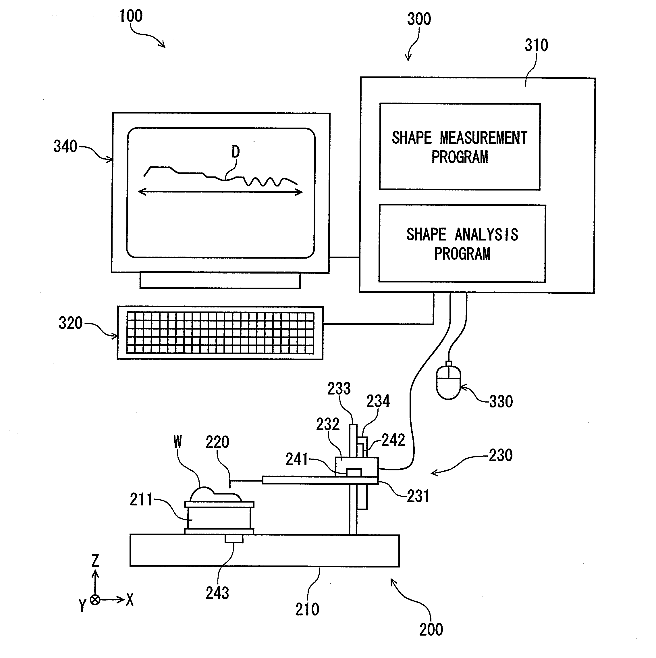
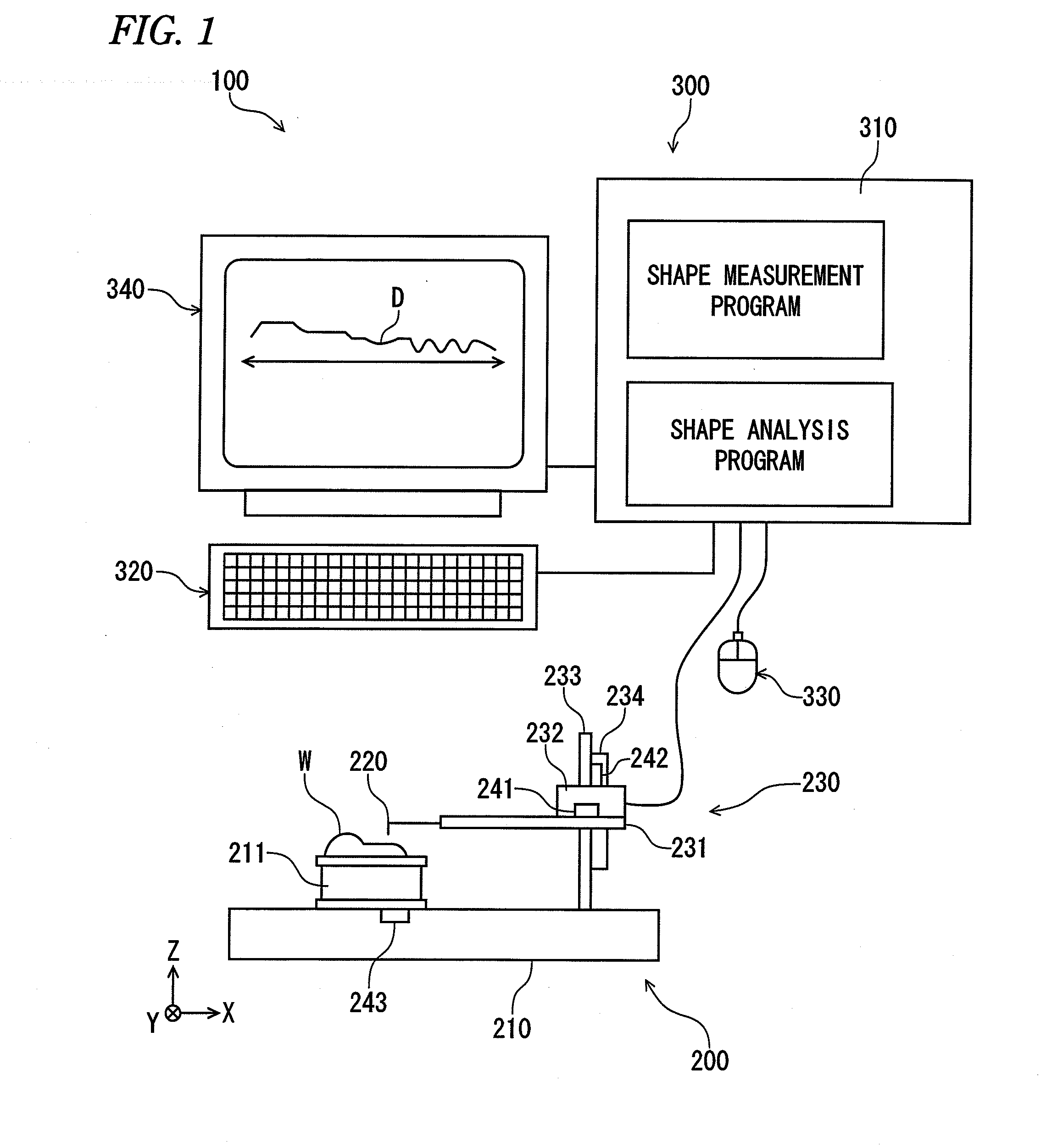
[0069]FIG. 1 is a diagram showing the whole configuration of a shape measuring system 100.
[0070]The shape measuring system 100 includes a shape measuring machine 200, and a computer system 300 for controlling this shape measuring machine 200.
[0071]A configuration of the shape measuring machine 200 is known, and will be described briefly.
[0072]The shape measuring machine 200 includes a table 210 on which work W is placed, a probe 220 for scanning a surface of the work placed on the table 210, a driving mechanism part 230 for moving the probe 220 with the probe 220 brought into contact with the work W, and sensors (241, 242, 243) for detecting a position of the probe 220.
[0073]On the table 210, the work W is placed on a placement stand 211, and this placement stand 211 is further placed on the table 210.
[0074]The driving mechanism part 230 includes a probe holding part 2...
embodiment
Outline of Embodiment
[0081]An outline of the embodiment will be described before detailed description using a functional block diagram or a flowchart.
[0082]The functional block diagram or the flowchart will be described below after the outline description. This is because previous understanding of the outline probably facilitates understanding of a meaning of the invention.
[0083]The embodiment is characterized by a shape analysis program.
[0084]Particularly, an evaluation range is generated semi-automatically. Typically, a user automatically generates an evaluation range to calculate geometric properties by only one click (or one tap) on a screen. Hence, shape analysis operation by the embodiment is called one-click operation. As geometric elements used in shape analysis, a circle, a line and a point are typically given.
[0085]An outline of a method for executing shape analysis using the circle, the line and the point with one click will be described sequentially.
[0086]In addition, in...
first operation example
[0136]A procedure of operation of the embodiment will be described.
[0137]The case of obtaining straightness of a line segment will be described as a first operation example.
[0138]The procedure of operation of the embodiment broadly includes initialization (ST100), work shape measurement (ST200), and shape evaluation analysis (ST300) as shown in a flowchart of FIG. 15.
[0139]In the initialization (ST100), conditions necessary for one-click operation are preset. The conditions include setting of a tolerance threshold (FIG. 10), priority of an evaluation range (FIG. 12) and setting of a shift amount (FIG. 13).
[0140]When the initialization (ST100) is completed, a shape of work W targeted for evaluation is measured. That is, contour shape data of the work W is acquired using the shape measuring machine shown in FIG. 1. The shape data is stored in memory (for example, nonvolatile memory) of the inside of the host computer 310.
[0141]In order to verify working accuracy of this work W after t...
PUM
 Abstract
Description
Claims
Application Information
 - R&D
- Intellectual Property
- Life Sciences
- Materials
- Tech Scout
- Unparalleled Data Quality
- Higher Quality Content
- 60% Fewer Hallucinations
Browse by: Latest US Patents, China's latest patents, Technical Efficacy Thesaurus, Application Domain, Technology Topic, Popular Technical Reports.
© 2025 PatSnap. All rights reserved.Legal|Privacy policy|Modern Slavery Act Transparency Statement|Sitemap|About US| Contact US: help@patsnap.com


