Blower assembly

a technology of blower assembly and assembly plate, which is applied in the direction of machines/engines, stators, liquid fuel engines, etc., can solve the problems of loss of increase in drag, noise, vibration, etc., and achieve the effect of maximizing the efficiency minimizing the noise, vibration and harshness of the blower assembly

Active Publication Date: 2014-01-02
HANON SYST
View PDF23 Cites 1 Cited by
  • Summary
  • Abstract
  • Description
  • Claims
  • Application Information

AI Technical Summary

Benefits of technology

[0005]It would be desirable to produce a blower assembly including a pre-swirler configured to cooperate with a blower wheel of th...

Problems solved by technology

If the air is not rotated sufficiently, an increase in drag, nois...

Method used


Image

  • Blower assembly
  • Blower assembly
  • Blower assembly

Examples


Embodiment Construction

[0013]The following detailed description and appended drawings describe and illustrate various exemplary embodiments of the invention. The description and drawings serve to enable one skilled in the art to make and use the invention, and are not intended to limit the scope of the invention in any manner.

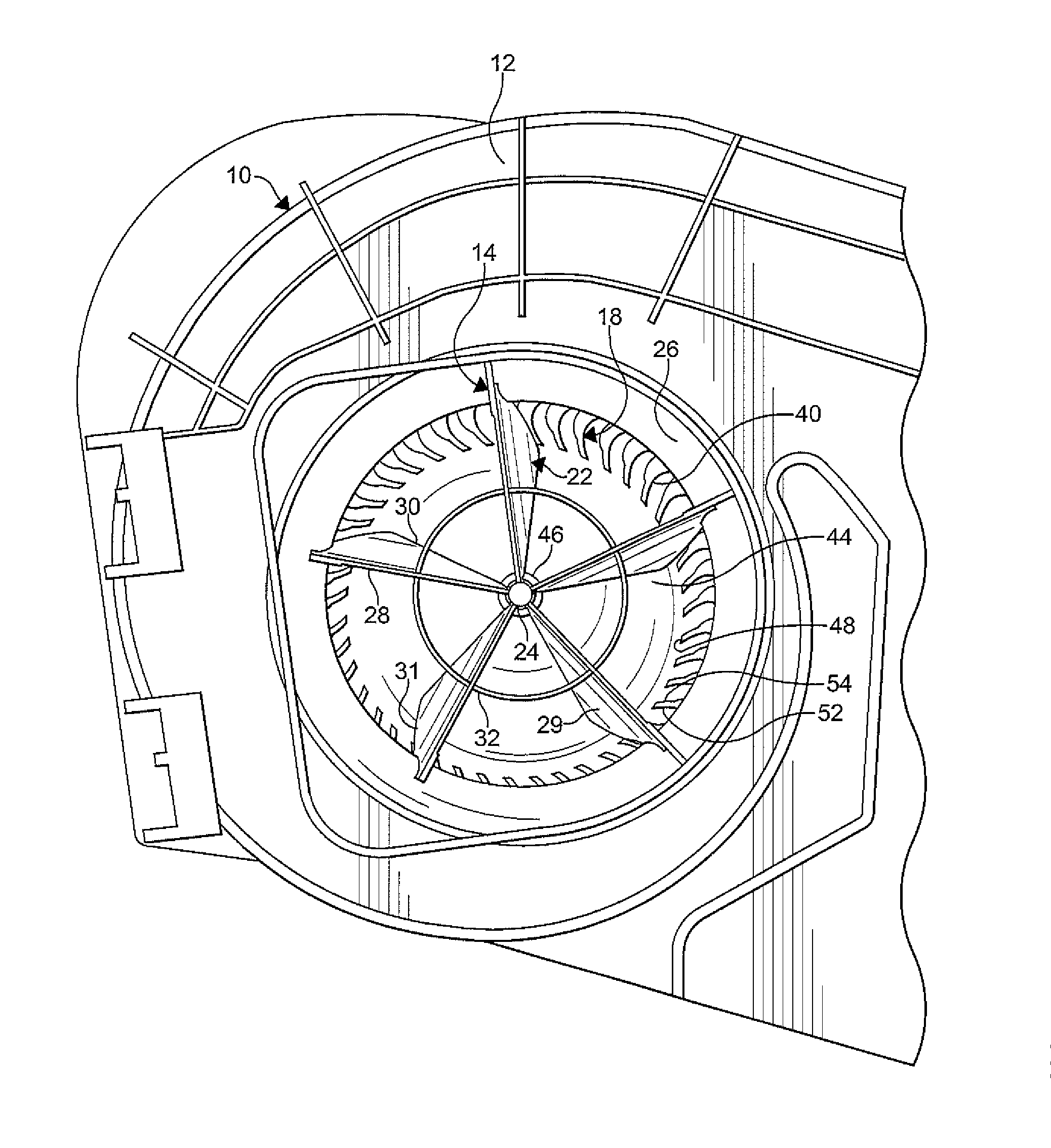
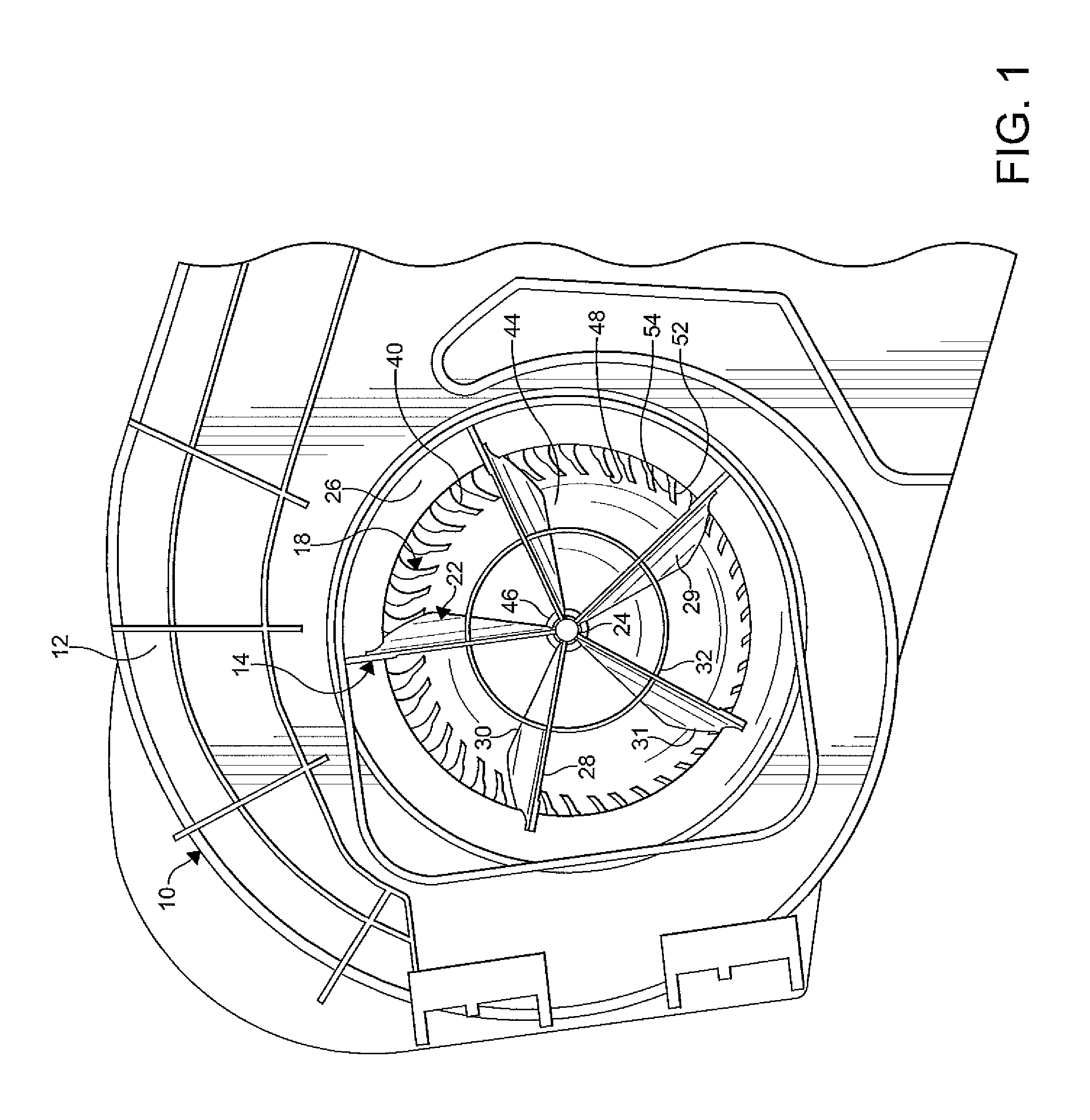
[0014]FIG. 1 shows a blower assembly 10 according to the present invention. The blower assembly 10 is configured to be employed in a climate control system of a vehicle (not shown). It is understood that the blower assembly 10 can be used in other applications and systems as desired. The blower assembly 10 shown includes a housing 12, a pre-swirler 14, and a blower wheel 18. It is understood that the blower assembly 10 can include other components as necessary for operation such as a motor for causing a rotation of the blower wheel 18, for example. The housing 12, the pre-swirler 14, and the blower wheel 18 shown are formed from plastic. However, it is understood that each of the hou...


PUM


Abstract

A blower assembly includes a housing having a blower wheel disposed therein and a pre-swirler disposed in a fluid inlet of the housing. The pre-swirler includes an array of spaced apart vanes extending radially outwardly from a central hub. The vanes extend from the hub to an outer ring that is attached to the housing of the blower assembly. The vanes are configured to cooperate with the blower wheel to minimize a noise, a vibration, and a harshness (NVH) of the blower assembly, while maximizing an efficiency thereof.

Description

CROSS-REFERENCE TO RELATED APPLICATION[0001]This application claims the benefit of U.S. Provisional Patent Application Ser. No. 61 / 666,377 filed Jun. 29, 2012, the entire disclosure of which is hereby incorporated herein by reference.FIELD OF THE INVENTION[0002]The invention relates to a blower assembly and more particularly to a blower assembly including a pre-swirler for causing air entering the blower assembly to change direction.BACKGROUND OF THE INVENTION[0003]Centrifugal blower assemblies are commonly used in the automotive, air handling, and ventilation industries for directing a forced flow of air through air conditioning components. In a typical blower assembly, air is caused to flow into a housing through an inlet aperture formed therein. The blower assemblies typically include an electrically driven blower wheel that rotates in a predetermined direction in the housing. The blower wheel includes one or more curved blades, which cause the air to flow into an inlet of the bl...

Claims


Application Information

Patent Timeline
IPC IPC(8): F04D29/24
CPCF04D29/245F04D29/162F04D29/444F05D2250/51F04D29/4213F04D29/242F04D29/441
Inventor IYER, JAYANTHI
Owner HANON SYST
Why Eureka
Try Eureka