Stake sharpening holder, skate blade, and method of use

a technology for skating blades and holder holders, which is applied in the direction of skis, sport apparatus, skates, etc., can solve the problems of blade sharpening or contouring being compromised, the number of problems, and the system of dowels using dowels 104 cannot work for these types of blades, so as to improve the sharpening and/or contouring process of skates

Inactive Publication Date: 2013-12-26
ALLEN ROBERT H
View PDF21 Cites 22 Cited by
  • Summary
  • Abstract
  • Description
  • Claims
  • Application Information

AI Technical Summary

Benefits of technology

[0008]The present invention is an improvement over prior art skate sharpening holders and their methods of use. Another aspect of the invention is an improved skate blade that can be used with the inventive skate sharpening holders to improve the sharpening and / or contouring process for skates.
[0009]One aspect of the invention includes a skate sharpening holder that is designed to engage a skate blade or runner (hereinafter called the skate blade) being held by the holder in order that the skate can be accurately sharpened and / or contoured. As part of this engagement, the anvil plate of the holder and the skate blade of the skate are specially configured so that the anvil plate and skate blade are engaged together to hold the skate blade in place on the holder in a secure fashion.
[0013]The invention also includes just the skate blade with the alignment holes or pins. Thus, the skate blade having a length direction extending between front and rear ends of the skate blade would include at least two alignment holes or pins, the alignment holes or pins being spaced apart and aligned along a length direction of the skate blade. The alignment holes or pins are sized to engage with corresponding alignment holes or pins on an anvil plate of a skate sharpening holder. The size of the alignment pins or holes on the skate blade permits a secure engagement with the anvil plate to hold the skate blade in place so that it can be sharpened or contoured without moving with respect to the anvil plate. The skate blade preferably has the spaced-apart alignment holes, which are preferably circular in shape.
[0015]The invention also includes making the alignment pins movable between a first position where at least a portion of the pin extends above the upper surface of the anvil plate so that the alignment pins can engage holes in the skate blade to retain the skate blade for sharpening and / or contouring, and a second position where the pin is positioned below the upper surface so that a skate blade without holes can rest on the upper surface of the anvil plate without interference from the alignment pins. The movable nature of the pins can be accomplished in any known fashion, with a preferred configuration using spring biasing to position the pins in the first position and then using an application of force, e.g., placing a skate blade on the tops of the pins to direct the pins into the second position so that the skate blade can rest on the upper surface of the anvil plate without interference from the pins during sharpening and / or contouring.

Problems solved by technology

The orientation of the skate blade with respect to the grinding wheel is critical, and if the blade and wheel are not properly aligned, the blade sharpening or contouring will be compromised.
The dowel system using dowels 104 cannot work for these types of blade.
The holder in Sakcriska has a number of problems since it is designed to interface with the skate blade holder in order to center the blade on the holder.
This is just not a practical approach for centering skates to a skate sharpening holder.

Method used


Image

  • Stake sharpening holder, skate blade, and method of use
  • Stake sharpening holder, skate blade, and method of use
  • Stake sharpening holder, skate blade, and method of use

Examples


Embodiment Construction

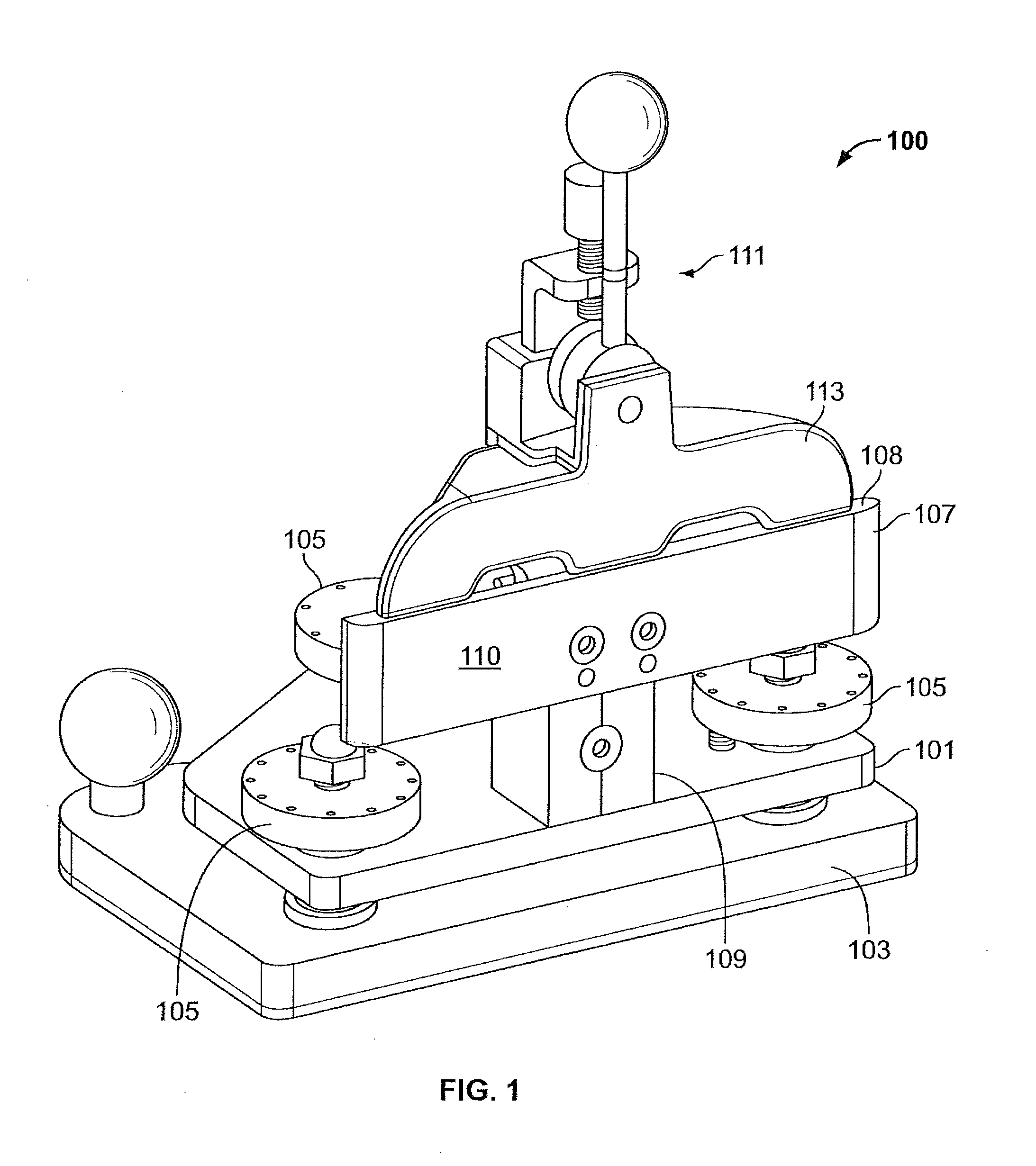
[0028]The invention provides significant improvements in the field of skate sharpening and contouring. By using the inventive skate sharpening holder and specially configured skate blades, a skate blade can be securely held or fixed on the holder during sharpening and / or contouring. Using prior art holders, it is often the practice to use the skate blade holder as a guide for the sharpening or contouring operation. However, the holder for one skate of a pair of skates may have a slightly different shape than the holder of the other skate in the pair. In this instance, conducting a contouring or sharpening operation on the one skate will not produce the same shape or contour on the other skate due to the difference between the two skate blade holders of the pair of skates. Even just a subtle difference in the skate blade holders for a pair of skates can result in a significant difference in the sharpened or contoured skate. Put another way, the pair of skates do not have the same con...


PUM

PropertyMeasurementUnit
diameteraaaaaaaaaa
circular cross sectional shapeaaaaaaaaaa
lengthaaaaaaaaaa

Abstract

A skate sharpening holder includes an anvil plate surface that is adapted to engage with a skate blade so that the skate blade is securely held with respect to the anvil during skate sharpening or contouring. The anvil plate surface can include pins or openings that would engage with respective openings or pins in a skate blade to hold the skate blade in place.

Description

FIELD OF THE INVENTION[0001]The present invention is directed to a skate sharpening holder and skate blade configuration, and particularly to a skate sharpening holder and skate blade that are configured to hold the blade with respect to an anvil plate of the holder for sharpening or contouring.BACKGROUND ART[0002]A number of skate sharpening fixtures have been developed for skate sharpening machines. These fixtures hold the skate blade in place while a grinding wheel or the like is used to sharpen or contour the skate blade. The orientation of the skate blade with respect to the grinding wheel is critical, and if the blade and wheel are not properly aligned, the blade sharpening or contouring will be compromised.[0003]Prior art fixtures offer control of the blade orientation, see for example, the Wissota and Blademaster fixtures, and U.S. Pat. No. 5,897,248 to Sacriska.[0004]FIG. 1 shows a perspective view of an exemplary skate sharpening fixture, which is designated by the referen...

Claims


Application Information

Patent Timeline
Patent Type & Authority Applications(United States)
IPC IPC(8): A63C1/30B24B1/00B24B9/04
CPCB24D15/066B24B3/003A63C3/10
Inventor ALLEN, ROBERT H.
Owner ALLEN ROBERT H
Why Eureka
Try Eureka