
Collapsible and re-expandable prosthetic heart valve cuff designs and complementary technological applications

a prosthetic heart valve and cuff technology, applied in the field of prosthetic heart valves, can solve the problems of significant limitations in the design of the cuff, significant challenges in the design of the expandable valve, and disrupt the electrical conduction system, and achieve the effect of encouraging intimate engagemen

Active Publication Date: 2013-12-19
ST JUDE MEDICAL LLC
View PDF2 Cites 81 Cited by
  • Summary
  • Abstract
  • Description
  • Claims
  • Application Information

AI Technical Summary

Benefits of technology

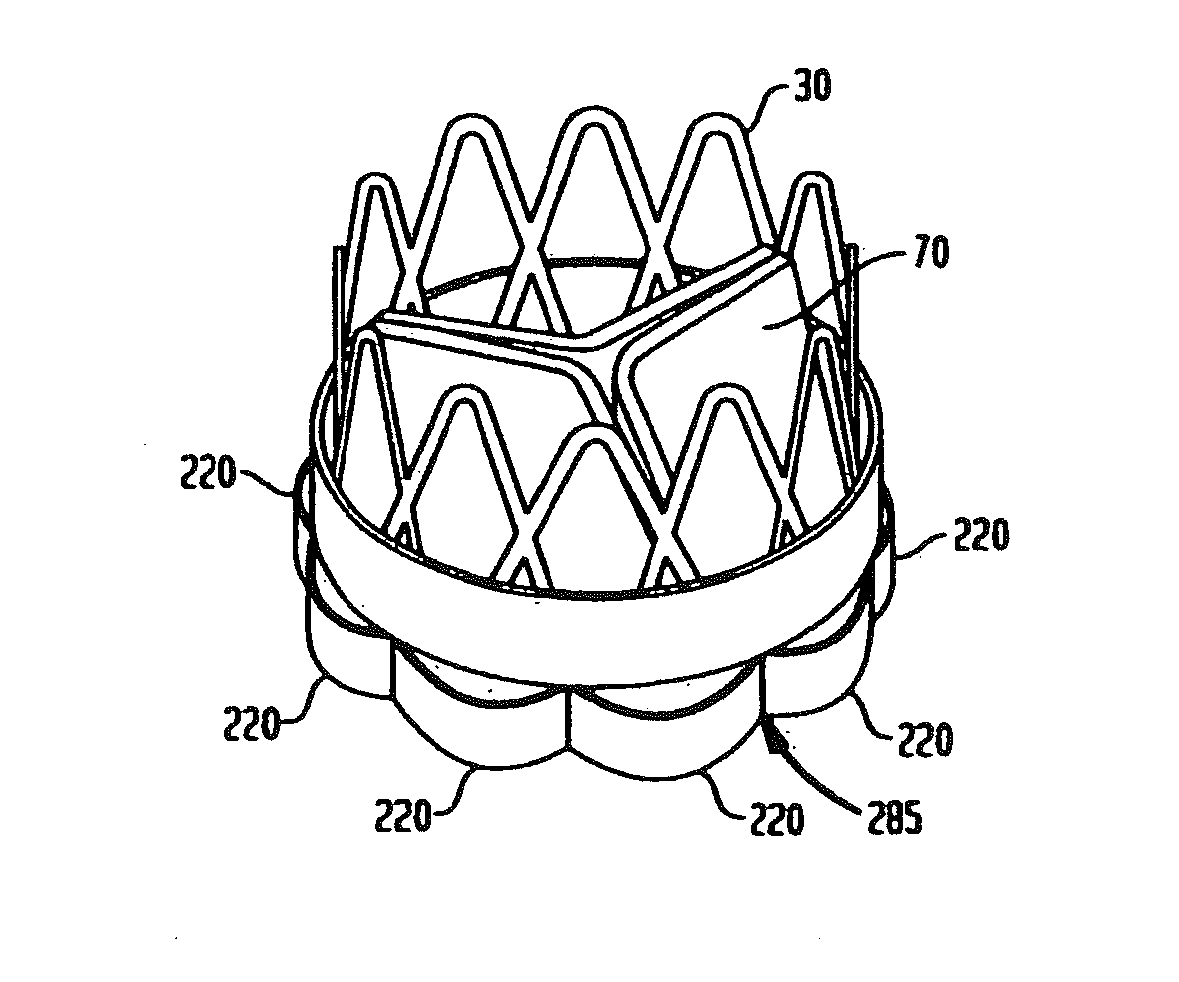
[0008]A further aspect of the invention provides a prosthetic valve which may have a stent body and valve element as discussed above. A valve according to this aspect of the invention desirably includes a cuff secured to the stent body and surrounding the annulus region, the cuff having one or more pleats adapted to collapse in axial directions and expand in radial directions upon transition of the stent body from the radially collapsed condition to the radially expanded condition. As further discussed below, the pleats can promote effective sealing with the surrounding native structures.
[0009]A valve according to yet another aspect of the invention desirably includes a stent body with a generally tubular annulus region having a proximal-to-distal axis, and desirably also includes prosthetic valve elements mounted to the stent body as discussed above. The valve according to this aspect of the invention most preferably has a cuff secured to the stent body and surrounding the annulus region; and also has one or more biasing elements separate from the cuff. The biasing elements are mechanically connected to the stent body and to the cuff, and are adapted to bias at least a portion of the cuff outwardly with respect to the stent body. Merely by way of example, the biasing elements may include springs formed separately from the stent body or integral with the stent body, and may also include a hygroscopic, water-swellable material disposed between the cuff and the stent body. By biasing the cuff outwardly from the stent body, the biasing elements tend to promote intimate engagement between the cuff and the surrounding tissues, even where then surrounding tissues are irregular.

Problems solved by technology

There are significant challenges in design of an expandable valve.
This imposes significant limitations on the design of the cuff as, for example, the thickness of the material which can be incorporated in the cuff.
Excessive forces on the annulus of the native aortic valve can disrupt the electrical conduction system of the heart and also can impair the functioning of the mitral valve.
These issues are complicated by the fact that the diseased native valve leaflets and other diseased tissues may present an implantation site which is irregular.
For example, patients with calcified or stenotic aortic valves may not be treated well with the current collapsible valve designs, and may encounter problems such as (1) perivalvular leakage (PV leak), (2) valve migration, (3) mitral valve impingement, (4) conduction system disruption, etc., all of which can lead to adverse clinical outcomes.

Method used


Image

  • Collapsible and re-expandable prosthetic heart valve cuff designs and complementary technological applications
  • Collapsible and re-expandable prosthetic heart valve cuff designs and complementary technological applications
  • Collapsible and re-expandable prosthetic heart valve cuff designs and complementary technological applications

Examples


Embodiment Construction

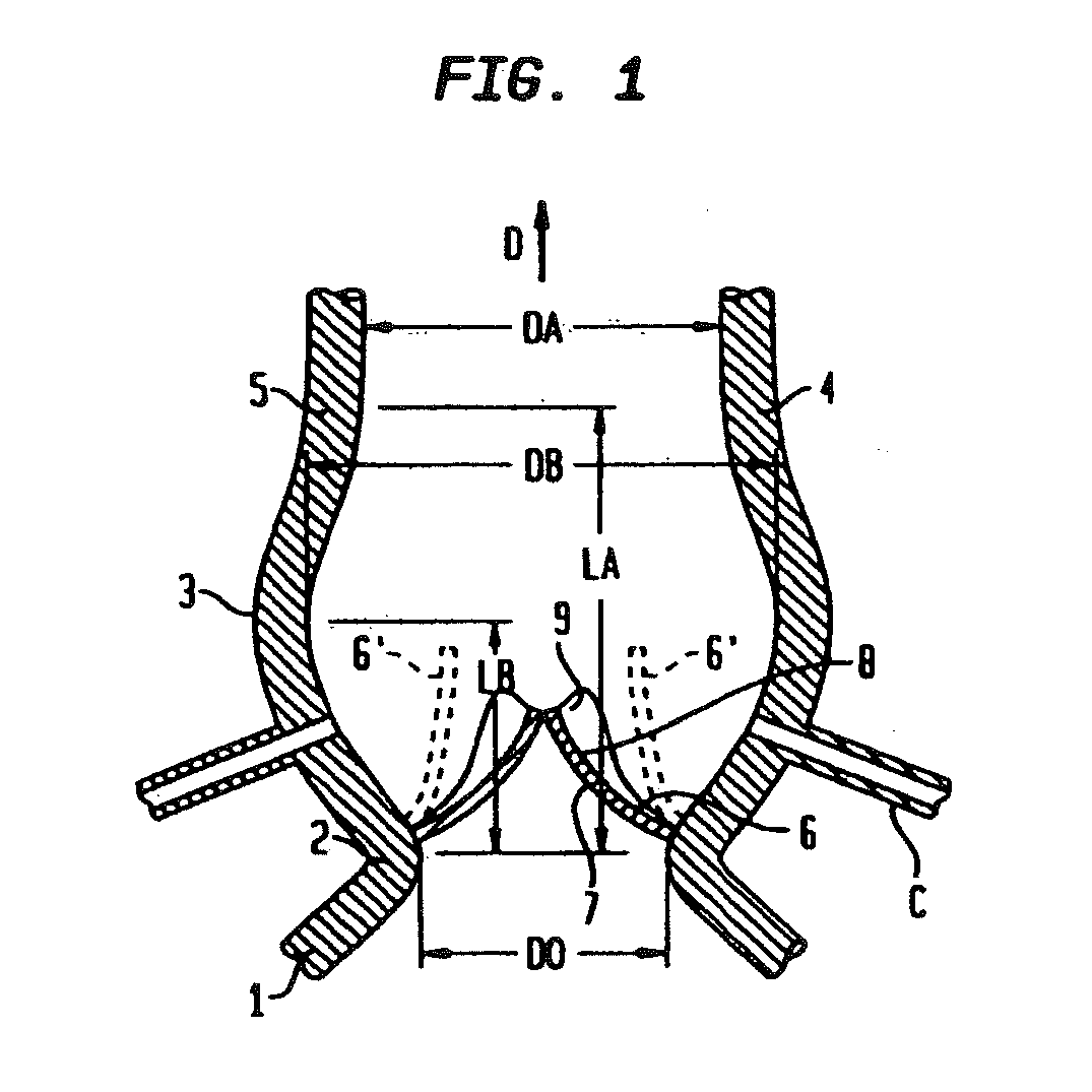
[0050]FIG. 1 is a simplified view of the geometry or anatomy of the aortic root tissue in a typical human heart. The left ventricular outflow tract (LVOT) 1 communicates with the ascending aorta 5 through the annulus 2 of the native aortic valve and the Valsalva sinus 3. The sinus joins the aorta at the sinotubular junction (STJ) 4. The native aortic valve typically includes three native valve leaflets 6, of which only two are visible in FIG. 1. As the left ventricle contracts during systole, blood is forced from the LVOT 1 through the native valve and sinus and into the aorta 5, moving generally in the downstream or antegrade flow direction indicated by arrow D. Each native valve leaflet has an interior surface 7 facing generally proximally and generally inwardly, toward the other native valve leaflets, and has an opposite-facing exterior surface 8. In a healthy individual, the native valve leaflets 6 open away from one another and move to the position schematically shown in broken...


PUM


Abstract

A prosthetic heart valve is provided with a cuff (85, 285, 400) having features which promote sealing with the native tissues even where the native tissues are irregular. The cuff may include a portion (90) adapted to bear on the LVOT when the valve is implanted in a native aortic valve. The valve may include elements (210, 211, 230, 252, 253) for biasing the cuff outwardly with respect to the stent body when the stent body is in an expanded condition. The cuff may have portions of different thickness (280) distributed around the circumference of the valve in a pattern matching the shape of the opening defined by the native tissue. All or part (402) of the cuff may be movable relative to the stent during implantation.

Description

CROSS-REFERENCE TO RELATED APPLICATIONS[0001]This application claims the benefit of the filing date of U.S. Provisional Patent Application No. 61 / 134,995 filed Jul. 15, 2008, the disclosure of which is hereby incorporated herein by reference.FIELD OF THE INVENTION[0002]The present invention is directed to prosthetic heart valves for replacement of native heart valves, to components for use in such prosthetic heart valves, and to methods of treating patients with such prosthetic heart valves.BACKGROUND OF THE INVENTION[0003]Certain prosthetic heart valves incorporate an expandable stent body and valve elements such as prosthetic valve leaflets mounted to the stent body. The prosthetic valve may also include a cuff including one or more layers of materials such as fabric or animal tissue. Valves of this type may be implanted in the heart by advancing the valve into the body of the patient with the stent body and cuff in a collapsed condition in which the stent body and cuff has a rela...

Claims


Application Information

Patent Timeline
Patent Type & Authority Applications(United States)
IPC IPC(8): A61F2/24
CPCA61F2/2409A61F2/2412A61F2250/0039A61F2220/0008A61F2220/0075A61F2230/0054A61F2250/0003A61F2/2418A61F2230/0069A61F2250/0069A61F2210/0014A61F2220/0016A61F2/2427A61F2/2433A61F2/2436A61F2/246A61F2/2442A61F2/2466A61F2/243
Inventor BRAIDO, PETER NICHOLASASHWORTH, PAUL EDWARDSCHRAUT, JULIA ANN
Owner ST JUDE MEDICAL LLC
Learn More