
Staple chamber assembly and linear surgical stitching device using said staple chamber assembly

Active Publication Date: 2013-12-12
TOUCHSTONE INTERNATIONAL MEDICAL SCIENCE CO LTD
View PDF12 Cites 19 Cited by
  • Summary
  • Abstract
  • Description
  • Claims
  • Application Information

AI Technical Summary

Benefits of technology

The invention aims to provide a staple cartridge assembly with a simple structure to prevent accidental firing and a linear surgical stapler that utilizes this assembly.

Problems solved by technology

Error firing action means that after the instrument has been fired, it refires without any nails in the reloading unit.
The consequence of such error firing action will extrude the nails which have already well closed and will cause over-deformation of the nails.
As a result, the wound closure cannot be good enough, and serious medical malpractices and sequelae sometimes occur.
However, in fact, such safely mechanism cannot absolutely avoid empty firing of the instrument between the time after the firing of the instrument is complete and before the instrument is opened.
Therefore, the conventional second error firing protection cannot continue the entire process between the time when the firing of the instrument is complete and before a new staple cartridge is installed.
Thus, certain operation risk still exists.

Method used


Image

  • Staple chamber assembly and linear surgical stitching device using said staple chamber assembly
  • Staple chamber assembly and linear surgical stitching device using said staple chamber assembly
  • Staple chamber assembly and linear surgical stitching device using said staple chamber assembly

Examples


first embodiment

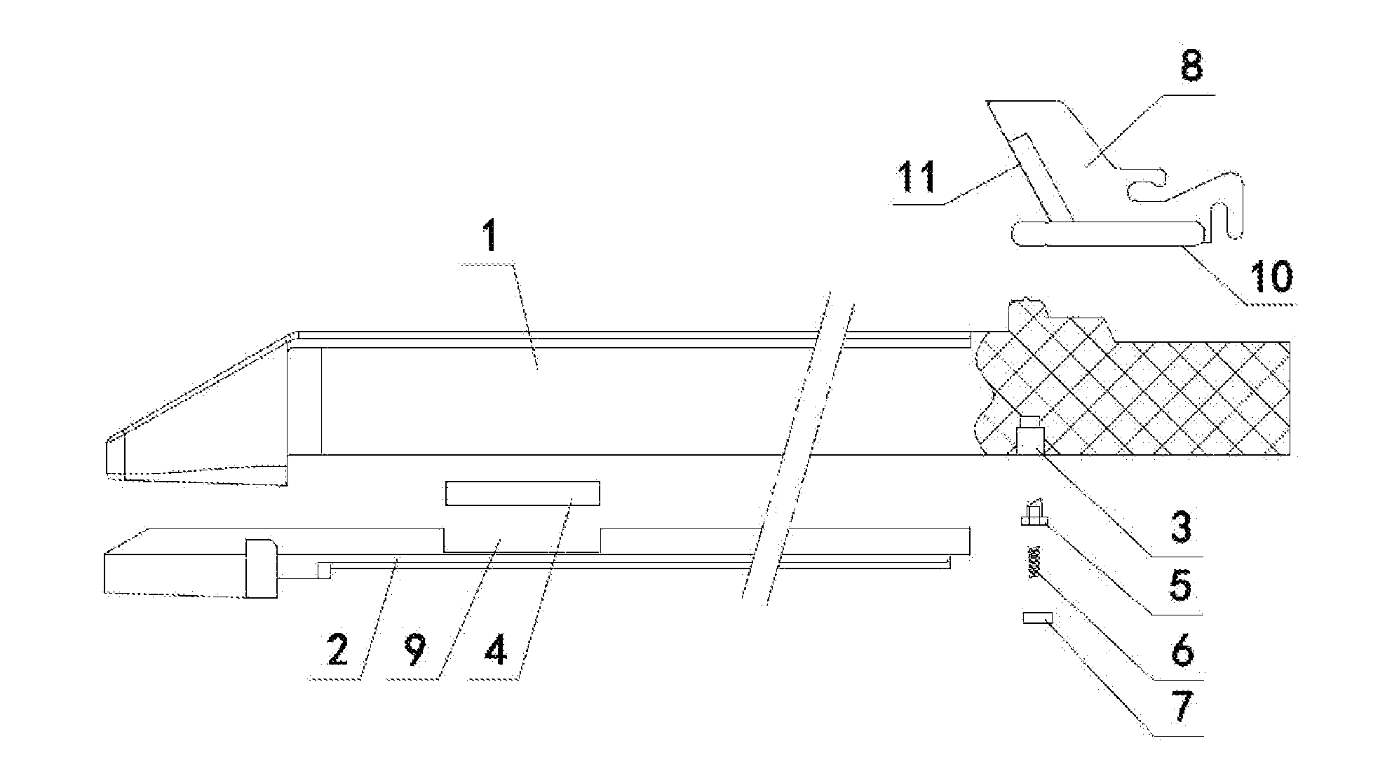
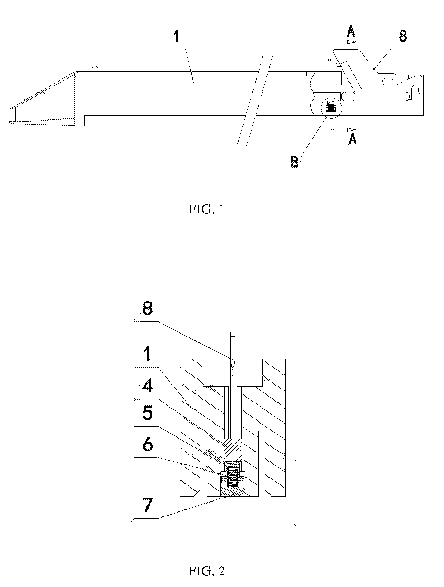
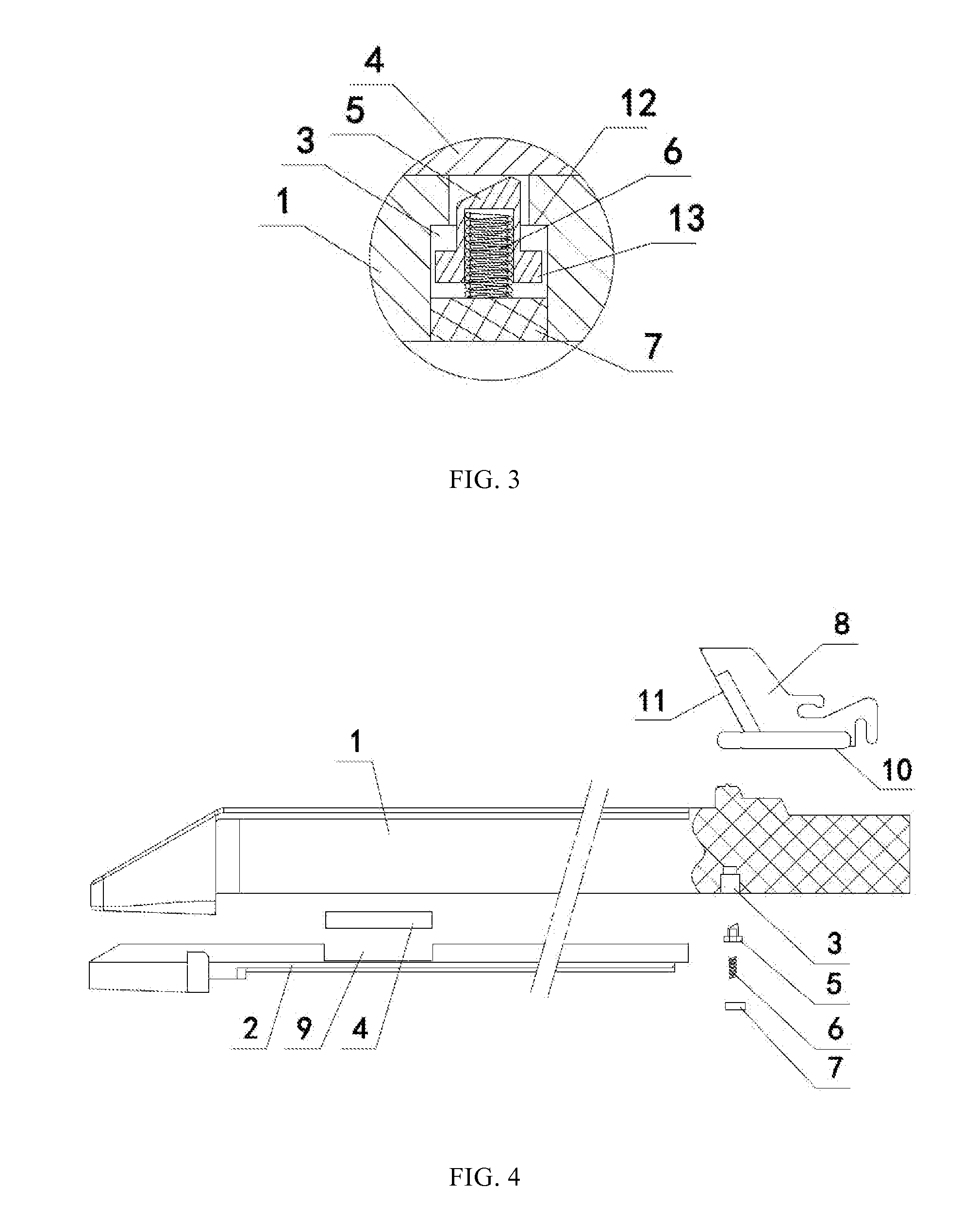
[0057]The staple cartridge 1 includes a through hole 3 located adjacent to a near-end bottom side of the staple cartridge 1. The through hole 3 is in communication with the cutting groove. According to the present application, a front-to-back direction means a left-to-right direction of the drawings, and a top-to-bottom direction means a top-to-bottom direction of the drawings. In a preferred embodiment, the through hole 3 is associated therein a moveable button 5 which is capable of reciprocating movement along an axis of the through hole. The bottom side of the moveable button 5 is provided with a spring 6. One end of the spring 6 abuts against the moveable button 5 so that the moveable button 5 always suffers a pushing force which directly tends towards the bottom surface 10. The bottom side of the spring 6 is provided with a cushion block 7 which is securely fixed to the bottom face of the staple cartridge 1. The other end of the spring 6 resists against a top surface of the cus...

second embodiment

[0062]Referring to FIGS. 5 and 6, according to the current embodiment, the elastic stopper includes a rotatable block 14 pivotally mounted in the staple cartridge and a torsion spring 15 acting on the rotatable block 14. The torsion spring 15 always applies an acting force for driving the rotatable block 14 rotating clockwise. The rotatable block 14 includes a limiting surface 16 for restricting movement of a cutter-pushing rod when the staple cartridge assembly is in the firing state. The sliding block 4 is located on top of the rotatable block 14 in the initial state.

[0063]When the staple cartridge assembly is in the initial state as shown in FIG. 5, the sliding block 4 presses against the rotatable block 14. When the staple cartridge is in the firing process, the sliding block 4 is pushed to move forwardly by the cutter 8. During sliding, the sliding block 4 will fall into the predetermined recess 9 to prevent the sliding block 4 from returning back to the initial position. In su...


PUM

PropertyMeasurementUnit
Pressureaaaaaaaaaa
Diameteraaaaaaaaaa
Elasticityaaaaaaaaaa

Abstract

A linear surgical stapler includes an upper staple cartridge receiving half-section, a lower staple cartridge receiving half-section and a staple cartridge assembly. The staple cartridge assembly includes a cutting groove in which a reciprocating movement cutter is mounted. The cutter includes a bottom surface and a knife blade located at a far end of the cutter. The staple cartridge assembly includes a restricting member mounted therein and an elastic stopper. The elastic stopper abuts against the restricting member when the staple cartridge assembly is in an initial state. The restricting member breaks away from the staple cartridge assembly when the staple cartridge assembly is in a firing complete state, thereby preventing the cutter from sliding towards the far end of the staple cartridge. As a result, misfiring throughout the whole operation of the linear surgical stapler is prevented.

Description

[0001]This application claims the benefit of priority to Chinese Patent Application No. 201010581554.7 titled “A KIND OF LINEAR SURGICAL STAPLER”, filed with the Chinese State Intellectual Property Office on Dec. 10, 2010, the entire disclosure of which is incorporated herein by reference.FIELD OF THE INVENTION[0002]The present invention relates to a staple cartridge assembly and a linear surgical stapler having such staple cartridge assembly, which belongs to the technical fields of medical devices.BACKGROUND OF THE INVENTION[0003]Surgical stitching instruments have been widely used in surgical operations for stitching up wounds, and stitching up and cutting interior tissues. U.S. Pat. No. 5,129,570 discloses a typical surgical stitching instrument which is provided with double functions of stitching and cutting. That is to say, the surgical stitching instrument is capable of stitching up wounds and simultaneously cutting spilth tissues. Such surgical stitching instruments usually ...

Claims


Application Information

Patent Timeline
IPC IPC(8): A61B17/072
CPCA61B17/07207A61B2017/07285A61B2090/08021
Inventor CHEN, WANGDONGPEI, YONGWANGZHOU, JING
Owner TOUCHSTONE INTERNATIONAL MEDICAL SCIENCE CO LTD
Learn More