
Orthodontic digital setups

a digital setup and orthodontic technology, applied in dental surgery, instruments, analogue processes for specific applications, etc., can solve the problems of difficult computer recognition of boundaries that separate a given tooth from adjacent teeth, affecting the efficiency of dental treatment, and affecting the quality of dental treatment, so as to reduce the area of mouth surface, reduce the difficulty of computer recognition, and improve the success rate of computerized segmentation.

Active Publication Date: 2013-12-05
3M INNOVATIVE PROPERTIES CO
View PDF15 Cites 167 Cited by
  • Summary
  • Abstract
  • Description
  • Claims
  • Application Information

AI Technical Summary

Benefits of technology

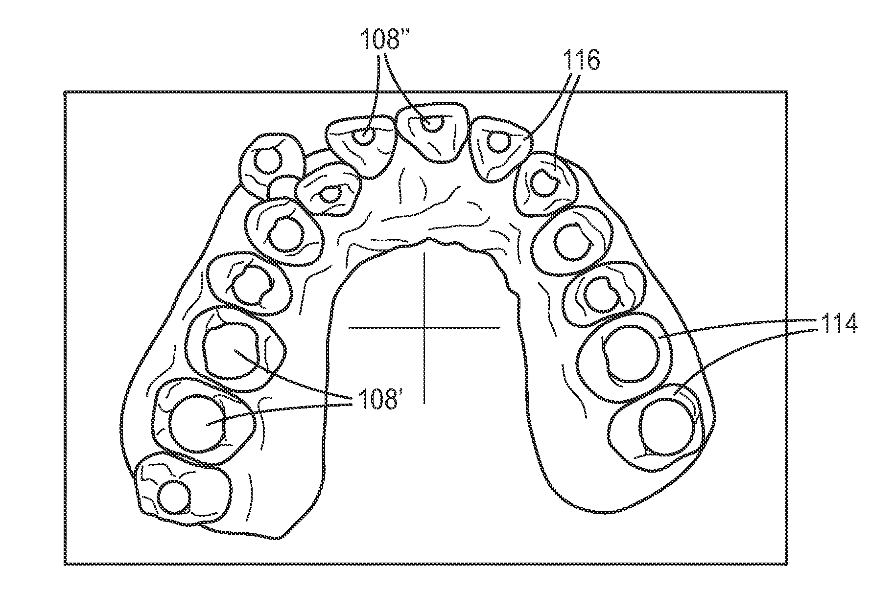
The patent describes a method for identifying a singular tooth surface on a mouth surface using a virtual surface. This method then automatically analyzes the remaining portions of the mouth surface to identify the boundaries that separate the tooth surface from surrounding mouth surfaces, thus defining segmented tooth objects. This approach leverages the knowledge of the user while retaining the advantages of a semi-automatic process, and improves the success rate of computerized segmentation by excluding certain surfaces that tend to induce error. Additionally, computing resources are significantly saved by reducing the area of mouth surface analyzed after each successive tooth has been identified.

Problems solved by technology

Some of the technically challenging aspects of digitally enabled orthodontics relate to the proper recognition of tooth objects in the segmentation process.
Teeth tend to display significant variability in size and shape, making it difficult for computers to recognize boundaries that separate a given tooth from adjacent teeth and other surrounding structure, such as gingival tissue.
Especially problematic are the chewing surfaces of teeth, which can be jagged, worn and unpredictable.
These can frustrate efforts by a computer to automatically separate tooth surfaces from surrounding structure.
While a human can easily isolate surfaces belonging to a single tooth, it can be time-consuming for a human to manually perform the segmentation process on an entire arch.

Method used


Image

  • Orthodontic digital setups
  • Orthodontic digital setups
  • Orthodontic digital setups

Examples


Embodiment Construction

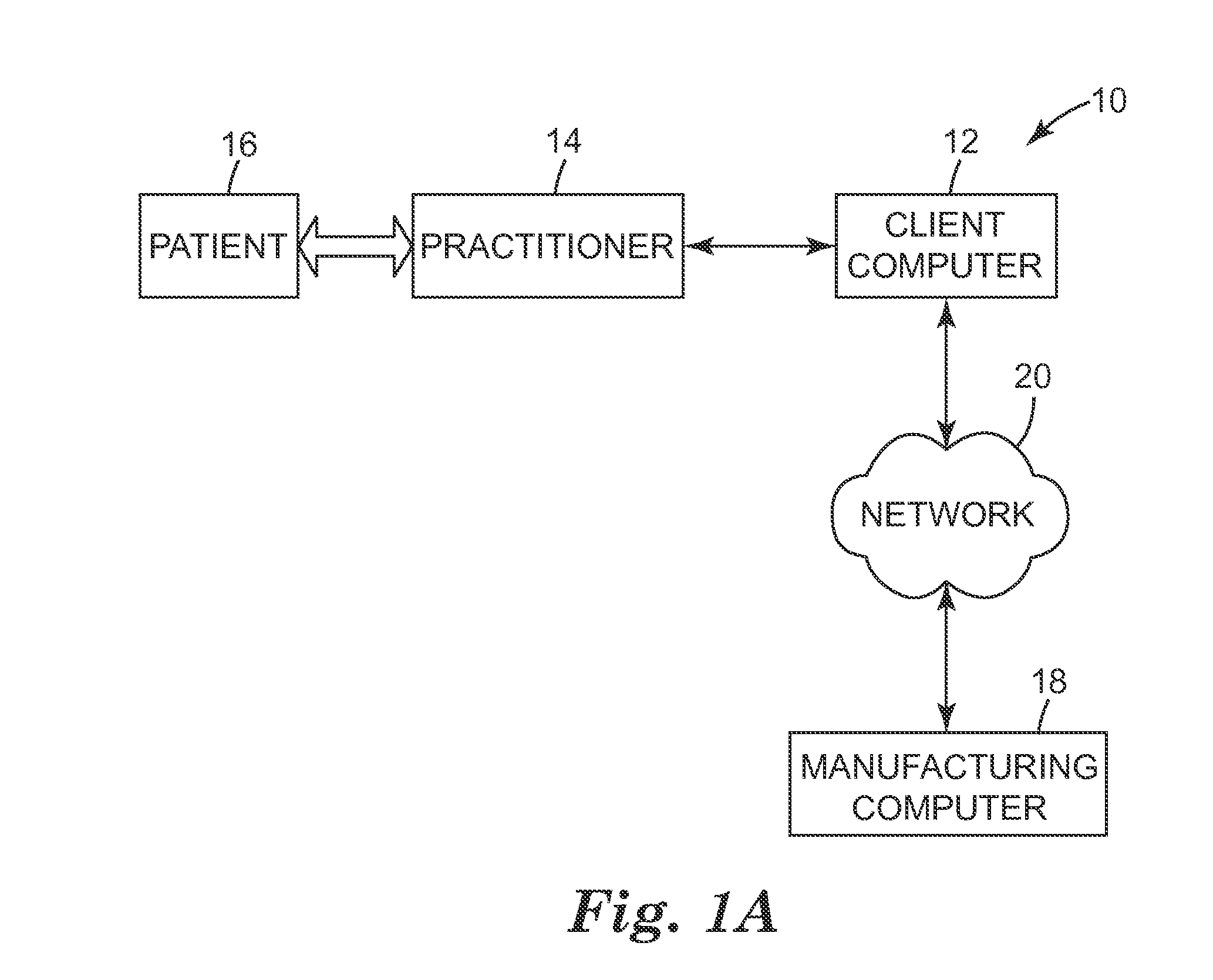
[0058]FIG. 1A is a block diagram illustrating an exemplary computer environment 10 that includes a client computer 12. Preferably, the client computer 12 has a processor, input device, memory, and display device. The client computer 12 presents an environment for an orthodontic practitioner 14 to interact with a digital representation of a portion of or an entire dental arch of patient 16 to generate and visualize an orthodontic digital setup for patient 16. Optionally and as shown, the client computer 12 communicates with a manufacturing facility 18 via network 20.

[0059]The client computer is operated by a user. The user interacts with modeling software executing on a computer to visualize, process, and manipulate the 3D representation of a patient's dental arch, arches, or subsets thereof. The computer may be located in the manufacturing facility 18, a dental laboratory, or practitioner's office. As another possibility, the computing resources for running the software may be sprea...


PUM


Abstract

Methods for recognizing a virtual tooth surface, defining a virtual tooth coordinate system, and simulating a collision between virtual teeth are provided. Methods include receiving input data specifying a point on the rendered surface model associated with a tooth, deriving a perimeter on the surface model of the tooth, and analyzing the surface model along a plurality of paths outwardly extending from points on the perimeter. Methods also include receiving point input data, receiving axis input data that defines first and second axes associated with the virtual tooth, computing a substantially normal vector for a portion of the tooth surface surrounding the point, and computing a coordinate system. Methods also include receiving permissible movement input data directed to permissible movement of a first virtual tooth, bringing the first virtual tooth into contact with a second virtual tooth, and displaying data resulting from the simulation.

Description

FIELD OF THE INVENTION Provided are methods related to digitally enabled orthodontics and, more particularly, computer-based methods for assisting orthodontic diagnosis and treatment.DESCRIPTION OF THE RELATED ART[0001]The field of orthodontics is concerned with repositioning a patient's teeth for improved function and aesthetic appearance. For example, orthodontic treatment often involves the use of tiny slotted appliances, known as brackets, which are generally fixed to the patient's anterior, cuspid, and bicuspid teeth. An archwire is received in the slot of each bracket and serves as a track to guide movement of the teeth to desired orientations. The ends of the archwire are usually received in appliances known as buccal tubes that are secured to the patient's molar teeth. The archwire and appliances are commonly referred to as “braces.” Orthodontic treatment may also be implemented through the use of clear plastic tooth positioning trays or other functional appliances.[0002]Th...

Claims


Application Information

Patent Timeline
IPC IPC(8): A61C7/00
CPCA61C7/002G06T19/00G06T2210/41G16H50/50G16B5/00A61C2007/004
Inventor SEE, PETERRABY, RICHARD E.STARK, NICHOLAS A.
Owner 3M INNOVATIVE PROPERTIES CO
Learn More