
Laparoscopic Manipulation

a technology of end effector and laparoscopic instrument, which is applied in the field of laparoscopic instruments, can solve the problems of affecting the ability of bone and bone structures to provide support and structure, and limiting the access to disc spa

Inactive Publication Date: 2013-12-05
GLOBUS MEDICAL INC
View PDF6 Cites 21 Cited by
  • Summary
  • Abstract
  • Description
  • Claims
  • Application Information

AI Technical Summary

Benefits of technology

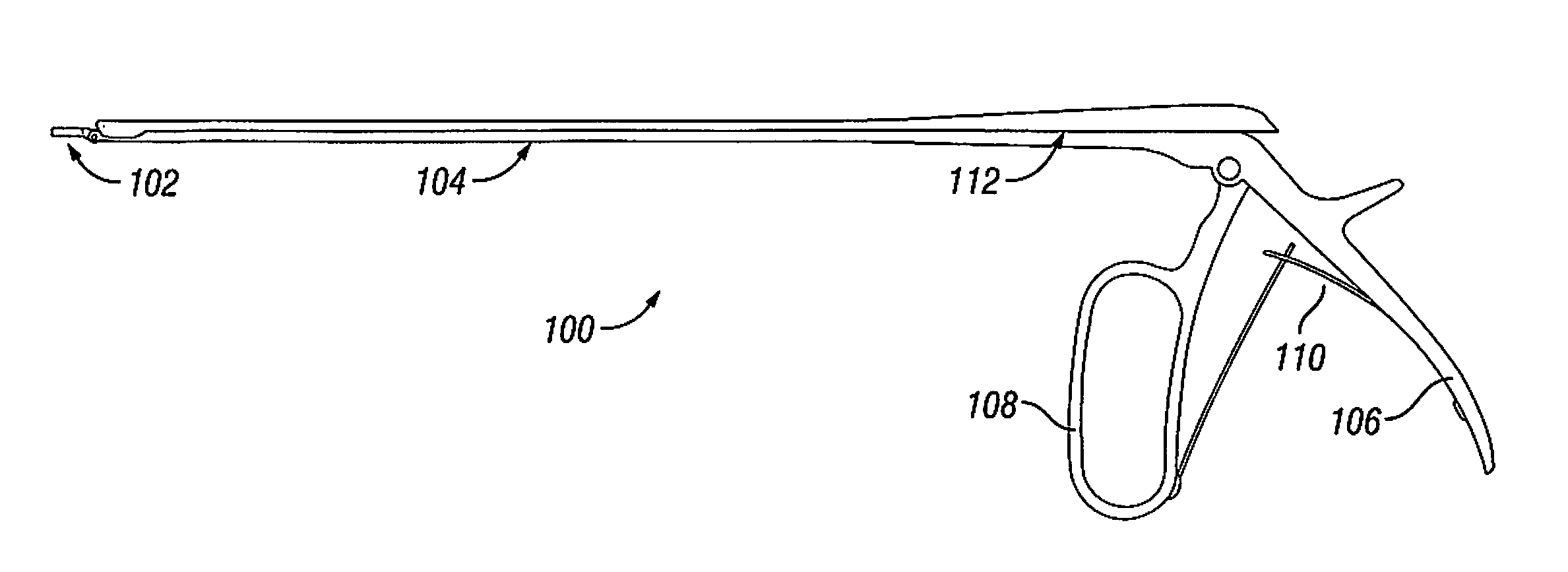
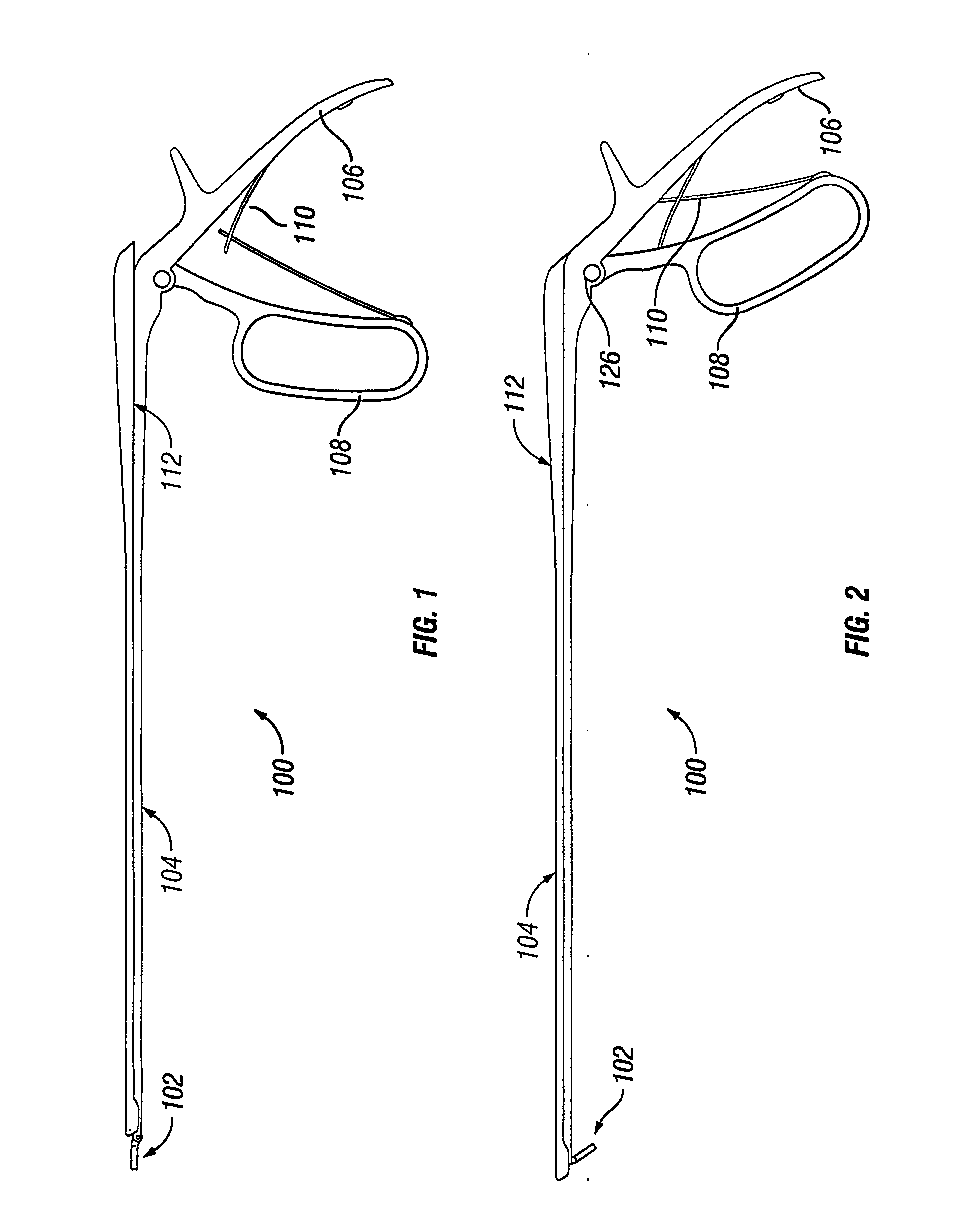
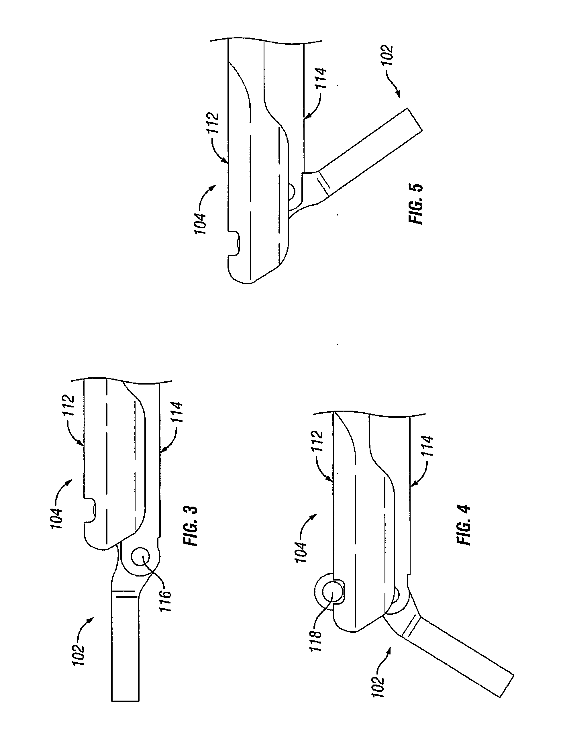
The patent describes a method for manipulating tissue inside a patient's body using two elongated extensions that are connected slidably. The second extension has a channel at its distal end. By sliding the first extension, a lever at the end of it can be moved to guide the movement of an end effector inside the patient. This allows for precise manipulation of tissue with minimal invasion.

Problems solved by technology

Bones and bony structures are susceptible to a variety of weaknesses that can affect their ability to provide support and structure.
Access to the disc space may be limited, as well, for example when conducting a minimally invasive procedure.

Method used


Image

  • Laparoscopic Manipulation
  • Laparoscopic Manipulation
  • Laparoscopic Manipulation

Examples


Embodiment Construction

[0032]As required, detailed embodiments are disclosed herein; however, it is to be understood that the disclosed embodiments are merely examples and that the systems and methods described below can be embodied in various forms. Therefore, specific structural and functional details disclosed herein are not to be interpreted as limiting, but merely as a basis for the claims and as a representative basis for teaching one skilled in the art to variously employ the present subject matter in virtually any appropriately detailed structure and function. Further, the terms and phrases used herein are not intended to be limiting, but rather, to provide an understandable description of the concepts.

[0033]The terms “a” or “an”, as used herein, are defined as one or more than one. The term plurality, as used herein, is defined as two or more than two. The term another, as used herein, is defined as at least a second or more. The terms “including” and “having,” as used herein, are defined as comp...


PUM


Abstract

A surgical instrument for use in a therapeutic treatment of a patient has a stem connected to a handle, and a slide connected to a trigger. An end effector forms a distal portion for manipulating body tissue, for example a curette, and a proximal portion that is pivotally connected to either the stem or slide. A lever extends from near the pivot and is engaged by the other of the stem or slide. When the slide and stem are slid relative to each other, the lever is engaged to pivot the end effector within the body, for example to cut tissue. A post on the lever engages a channel in the stem or slide, to guide movement of the end effector. A link may be pivotally connected between the lever and a stem or slide, to increase a range of motion of the end effector.

Description

FIELD OF THE INVENTION[0001]The invention relates to manipulating an end effector within the body, and more particularly to a laparoscopic instrument having an end effector such as a curette having a wide angle of movement.BACKGROUND OF THE INVENTION[0002]Bones and bony structures are susceptible to a variety of weaknesses that can affect their ability to provide support and structure. Weaknesses in bony structures have numerous potential causes, including degenerative diseases, tumors, fractures, and dislocations. Advances in medicine and engineering have provided doctors with a plurality of devices and techniques for alleviating or curing these weaknesses.[0003]In some cases, the spinal column requires additional support in order to address such weaknesses. One technique for providing support is to extend a structure between adjacent bones, the structure connected at each end to a polyaxial screw “tulip”, or yoke, connected to a bone screw inserted within the bone.[0004]Preparatio...

Claims


Application Information

Patent Timeline
Patent Type & Authority Applications(United States)
IPC IPC(8): A61B17/00A61B17/32
CPCA61B17/0218A61B17/025A61B2017/0256A61B17/320016A61B17/320708A61B2017/00261A61B2017/2927A61B17/1604A61B17/1617A61B17/1671A61B2090/0811
Inventor WEIMAN, MARK
Owner GLOBUS MEDICAL INC
Learn More