
Apparatus and method for simultaneously reducing glare and viewing a liquid crystal display

a liquid crystal display and glare reduction technology, applied in the field of polarized sunglasses, can solve the problems of reducing driving safety, criticized the increasing number of so-called dash-apps, and reducing the use of numerous displays

Inactive Publication Date: 2013-12-05
COLLETT EDWARD
View PDF4 Cites 5 Cited by
  • Summary
  • Abstract
  • Description
  • Claims
  • Application Information

AI Technical Summary

Benefits of technology

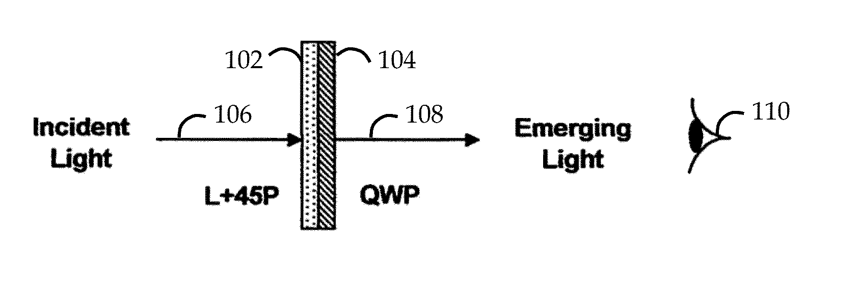
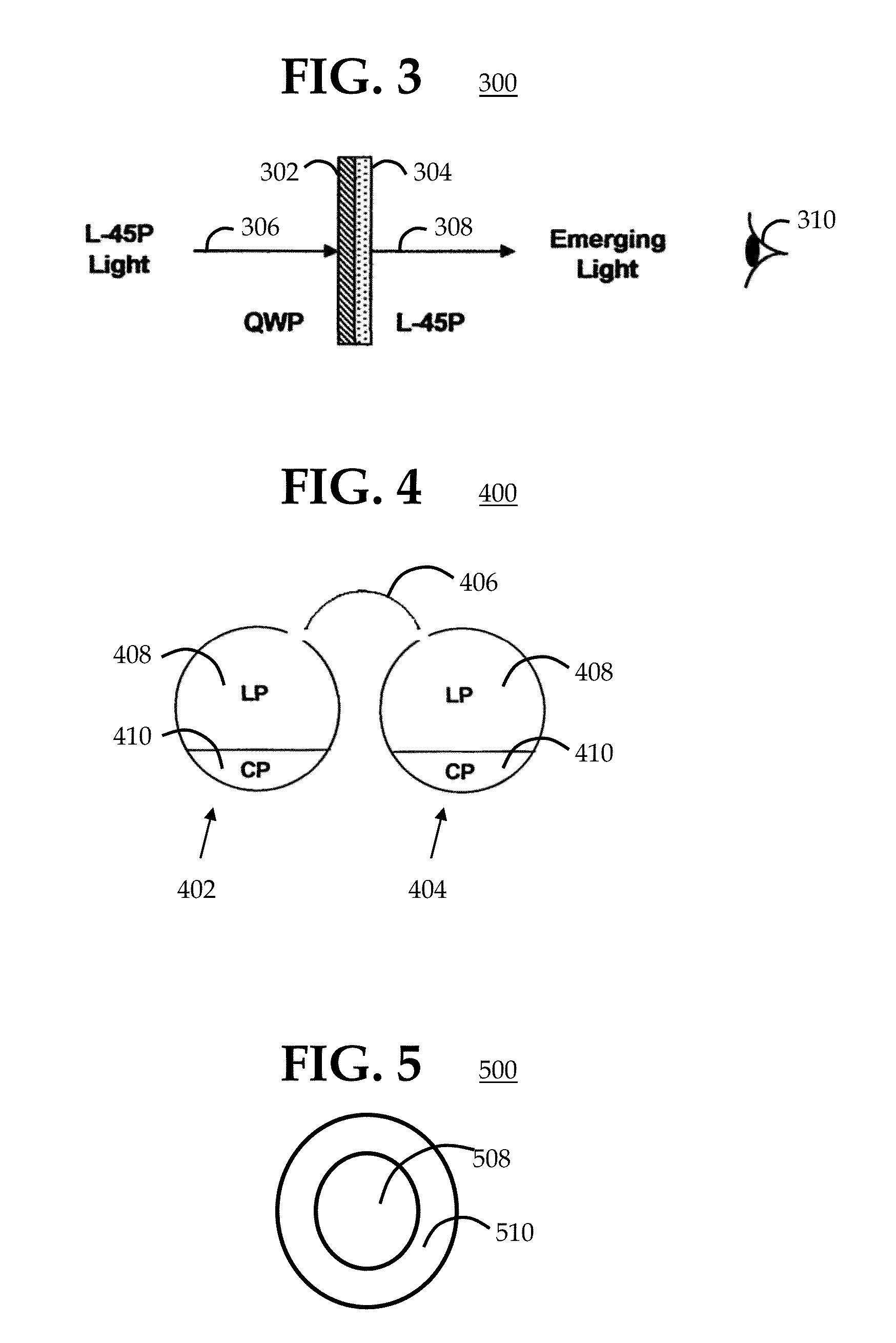
The present invention provides a way to create circular polarizers by combining a linear polarizer and a quarter-waveplate. This results in a polarized sunglass that blocks glare and allows the driver to view an LCD display simultaneously without needing to remove or move the sunglasses. The driver can shift their eyes or head to view the LCD display in a different direction.

Problems solved by technology

This transformation to the usage of numerous displays has been highly criticized by regulatory automobile organizations.
The National Highway Traffic Safety Administration has criticized the increasing number of so-called dash-apps.
Their sheer number has become overwhelming and has led to distractions and reduced driving safety.
Indeed, N.H.T.S.A. even regards navigation as interfering inherently with a driver's ability to safely control the vehicle.
If the driver views the display while he or she is driving, the LCD display may be blocked by the linear polarized sunglasses and artifacts such as dark patches may appear on the display.
The result is that for several seconds when driving in a glare environment, the driver is distracted from viewing the road, which exacerbates the dangerous and life threatening conditions noted by the N.H.T.S.A.
A drawback of this solution is that for comfortable viewing, the tint and the optical transmission of the lower part of the sunglass using a non polarizing material must be substantially identical to the tint and transmission in the upper polarizing element.

Method used


Image

  • Apparatus and method for simultaneously reducing glare and viewing a liquid crystal display
  • Apparatus and method for simultaneously reducing glare and viewing a liquid crystal display
  • Apparatus and method for simultaneously reducing glare and viewing a liquid crystal display

Examples


Embodiment Construction

[0025]In the following detailed description, numerous specific details are set forth in order to provide a thorough understanding of embodiments or other examples described herein. In some instances, well-known methods, procedures and components have not been described in detail, so as to not obscure the following description. Further, the examples disclosed are for exemplary purposes only and other examples may be employed in lieu of, or in combination with, the examples disclosed. It should also be noted the examples presented herein should not be construed as limiting of the scope of embodiments of the present invention, as other equally effective examples are possible and likely.

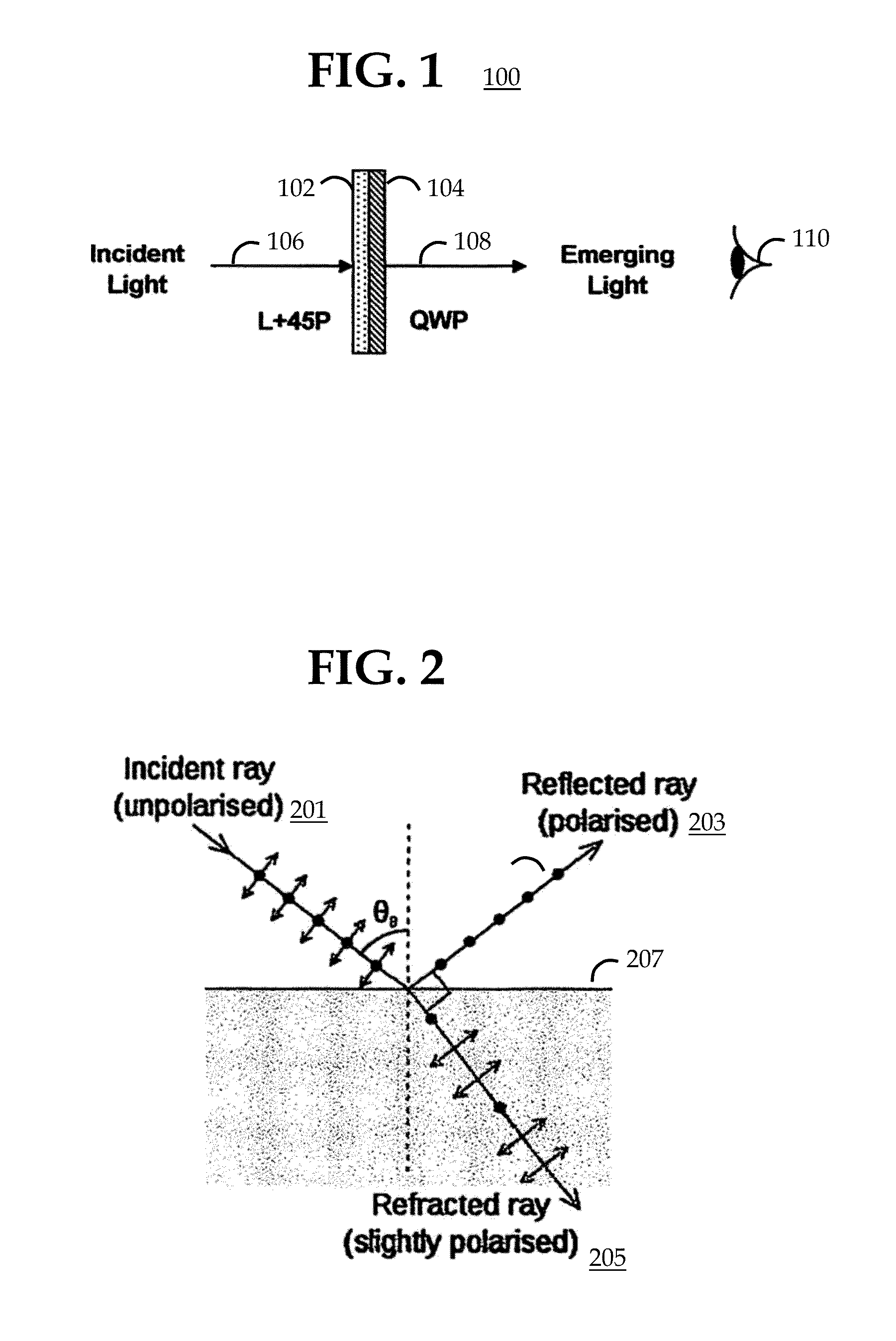
[0026]Embodiments in accordance with the present invention disclose a dual-polarized sunglass, which is a new type of sunglass that can overcome both polarization from reflected sunlight (i.e., glare) and is compatible with the linear polarized light emitted by LCD displays. The sunglass may be fitted in...


PUM


Abstract

Embodiments are described that simultaneously block glare arising from the reflection of polarized sunlight and can also allow a polarized liquid crystal display (LCD) to be clearly viewed. Embodiments may be useful for use as polarized sunglasses. Embodiments operate by using a unique property of a circular polarizer. One side of the circular polarizer substantially blocks the transmission of incident polarized light whereas the other side allows substantially complete transmission of incident polarized light. Using these opposite behaviors, polarizing sunglasses can be constructed in which the top portion uses a first side of the circular polarizer to block the polarized glare and the lower portion uses a second side of the circular polarizer, opposite from the first side, to view the LCD. Because two different polarizers are used, these sunglasses are called dual-polarization sunglasses to differentiate them from the traditional linear polarizer sunglasses

Description

CROSS-REFERENCE TO RELATED APPLICATIONS[0001]This application claims the benefit of U.S. Provisional Patent Application Ser. No. 61 / 686,071, filed on May 29, 2012, the entire content of which is hereby incorporated by reference in its entirety.BACKGROUND[0002]1. Field of the Invention[0003]This invention relates to polarized sunglasses that can be used to simultaneously block the glare arising from unpolarized sunlight reflected from a planar surface, while allowing for the reading of liquid crystal displays (LCDs) without the need for substantial movement of the polarized sunglasses.[0004]2. Description of Related Art[0005]Polarized sunglasses have been available for many years, in which polarized lenses have been used to filter out undesirable reflections, e.g., glare, and to reduce eye strain and fatigue. In addition, because polarizing sunglasses are tinted or appear to be tinted, the transmitted intensity is reduced, thereby allowing further reduction in eye fatigue. The use of...

Claims


Application Information

Patent Timeline
Patent Type & Authority Applications(United States)
IPC IPC(8): G02C7/12
CPCG02C7/12
Inventor COLLETT, EDWARD
Owner COLLETT EDWARD
Learn More