
Pool Cleaner Light Module

Active Publication Date: 2013-12-05
PENTAIR WATER POOL & SPA INC
View PDF5 Cites 18 Cited by
  • Summary
  • Abstract
  • Description
  • Claims
  • Application Information

AI Technical Summary

Benefits of technology

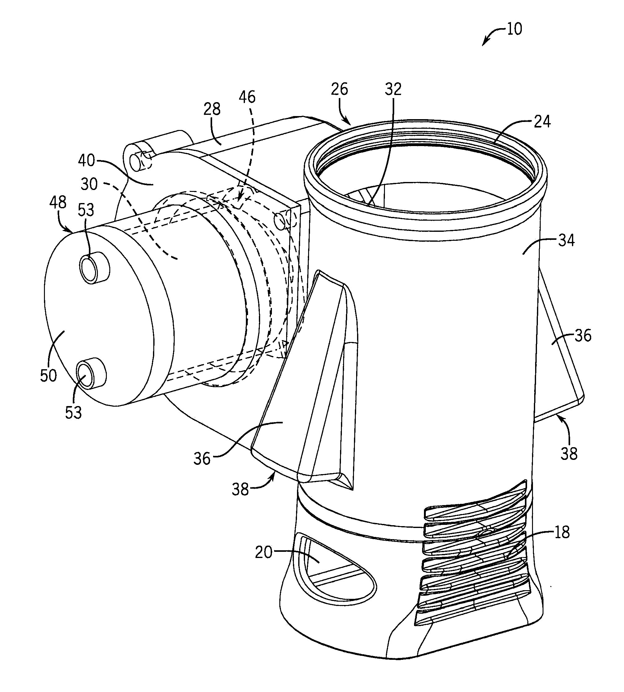
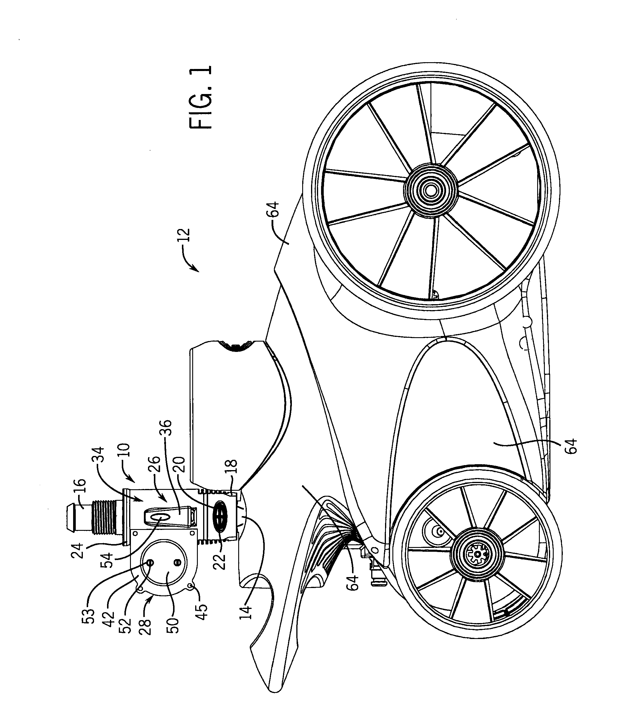
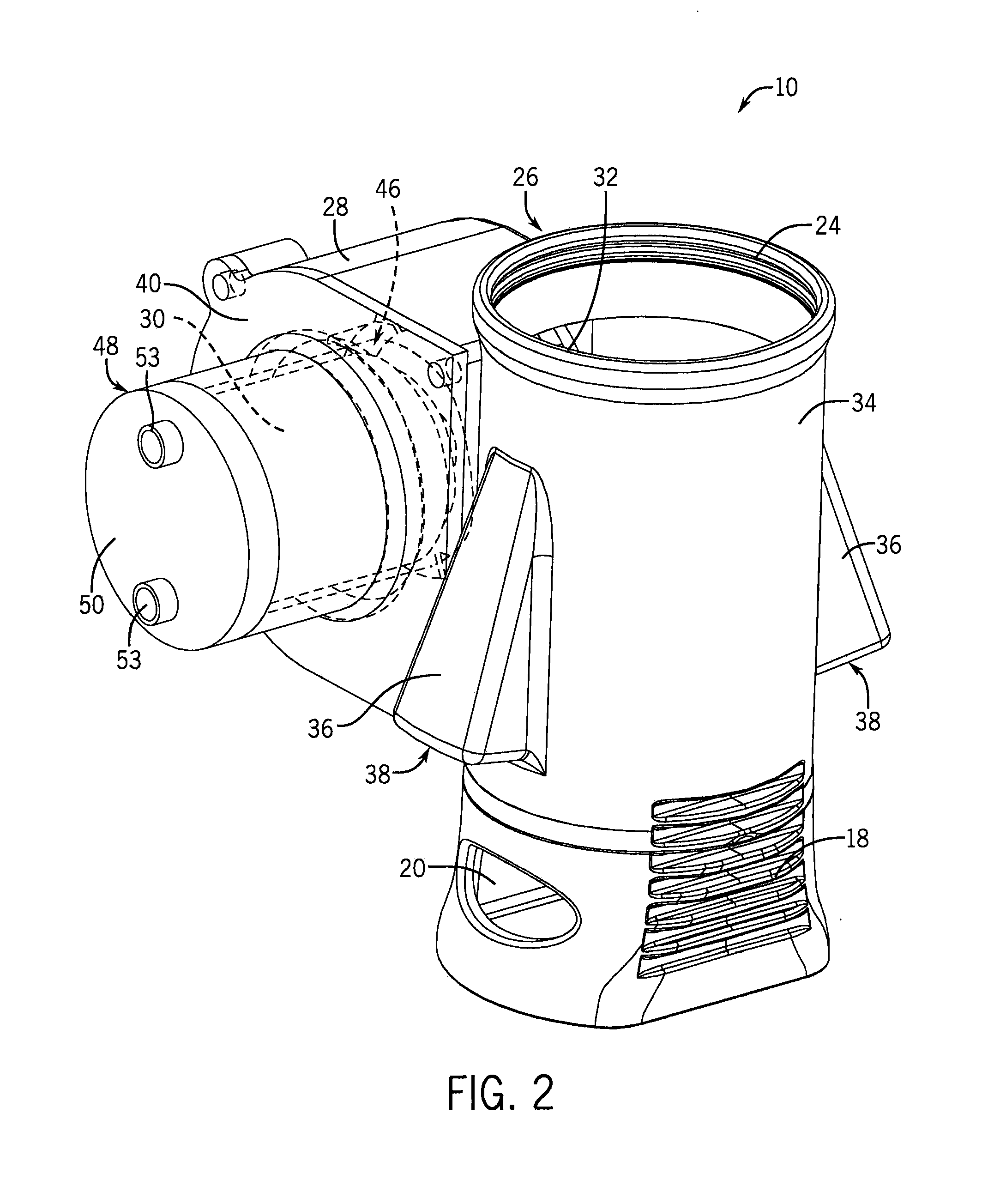
This patent describes a light module for a swimming pool cleaner that uses a paddle wheel to generate power from fluid flow through the cleaner. The generated power is then used to illuminate an area adjacent to the pool cleaner. The light module can be easily attached to the pool cleaner and can be used in conjunction with a pool hose to provide lighting for the pool. The light module can also be adjusted based on the pressure of the fluid flow to provide different lighting modes. The technical effects of this invention include improved visibility and safety when using a swimming pool cleaner, especially in low-light settings.

Problems solved by technology

Although automatic swimming pool cleaners operate with little manual operator interaction, it is sometimes difficult for the operator to quickly determine whether the pool cleaner is operating correctly or efficiently.
This may be due to mechanical malfunctions in robotic cleaners, or insufficient suction or pressure in suction-driven or pressure-driven pool cleaners.
This can be a tedious task that many operators do not pay attention to and, as a result, these operators do not realize their pool cleaner has not been operating until a substantial amount of debris has settled on the pool floor.

Method used


Image

  • Pool Cleaner Light Module
  • Pool Cleaner Light Module
  • Pool Cleaner Light Module

Examples


Embodiment Construction

[0015]Before any embodiments of the invention are explained in detail, it is to be understood that the invention is not limited in its application to the details of construction and the arrangement of components set forth in the following description or illustrated in the following drawings. The invention is capable of other embodiments and of being practiced or of being carried out in various ways. Also, it is to be understood that the phraseology and terminology used herein is for the purpose of description and should not be regarded as limiting. The use of “including,”“comprising,” or “having” and variations thereof herein is meant to encompass the items listed thereafter and equivalents thereof as well as additional items. Unless specified or limited otherwise, the terms “mounted,”“connected,”“supported,” and “coupled” and variations thereof are used broadly and encompass both direct and indirect mountings, connections, supports, and couplings. Further, “connected” and “coupled”...


PUM


Abstract

Embodiments of the invention provide a light module for a pool cleaner. The light module can include a housing, a paddle wheel, a generator, and at least one light emitting diode (LED). The housing can be removably coupled to the pool cleaner and can include a flow directing portion positioned in a fluid path of the pool cleaner. The paddle wheel can be located adjacent to the flow directing portion and can rotate in response to fluid flow through the fluid path. The generator can be coupled to the paddle wheel and can generate power through rotation of the paddle wheel. The LED can be coupled to the generator and can receive the generated power from the generator to illuminate an area adjacent to the pool cleaner.

Description

BACKGROUND[0001]Automatic swimming pool cleaners include components for driving the pool cleaners along the floor and sidewalls of a swimming pool, either in a random or deliberate manner, to vacuum debris on and adjacent to the floor and sidewalls. For example, conventional pressure side cleaners and suction cleaners often use hydraulic turbine assemblies as drive systems to drive one or more wheels. Robotic cleaners often include a motor or other mechanical system powered by an external power source to drive one or more wheels.[0002]Although automatic swimming pool cleaners operate with little manual operator interaction, it is sometimes difficult for the operator to quickly determine whether the pool cleaner is operating correctly or efficiently. For example, an operator can see the pool cleaner moving along a swimming pool floor, but not realize that the cleaner is not vacuuming or barely vacuuming until hours or days later when a substantial amount of debris has settled on the ...

Claims


Application Information

Patent Timeline
IPC IPC(8): A47L9/30H05B37/02
CPCE04H4/1654A47L9/30E04H4/148F21S9/046
Inventor DEERY, BRIANLIPSKI, JOHNRICHIUSO, LEONARDGOPALAN, SURESH
Owner PENTAIR WATER POOL & SPA INC
Learn More