
Mirror construction for concentrated solar systems by frc and applications

a concentrated solar system and mirror technology, applied in the field of solar mirrors, can solve the problems of high cost of polycarbonate panels, complex and expensive process for forming them according to desired curvature, and insufficient capital utilization, so as to reduce the overall cost of transportation, cost effective, and long service life

Inactive Publication Date: 2013-11-28
THARISAYI GEORGE PHILIP
View PDF0 Cites 6 Cited by
  • Summary
  • Abstract
  • Description
  • Claims
  • Application Information

AI Technical Summary

Benefits of technology

The invention is a solar mirror that is built into a building and can be used to reflect sunlight for use in concentrated solar power and photovoltaic systems. This reduces the cost and land requirements of these systems. The solar mirror is made of fiber reinforced concrete, which is cost-effective and durable. Overall, this invention provides a cost-effective and long-lasting solution for generating solar energy.

Problems solved by technology

Concentrated solar power system (CSP) and concentrated photovoltaic systems (CPV) provide an efficient means of utilizing the non-conventional energy resources but they are capital intensive and therefore not currently widely deployed.
Recent studies have shown that the majority of cost for a CPV or CSP system is represented by the concentrator (i.e mirrors).Another factor contributing to cost of these systems is their requirement for fair amount of land for their installation
The use of such mirror-finished plates has the drawback that the process for forming them according to the desired curvature is complicated and expensive.
However the high cost of polycarbonate panels and their manufacturing process which is not very environmental friendly do not make them an idle candidate to be used in solar heating elements.
This reduces the cost of CSP and CPV systems to some extent nevertheless the incurring cost involved in the transportation and installation of CSP and CPV apparatus and a considerable land usage by these systems still contribute a substantial amount to the cost of these systems.

Method used


Image

  • Mirror construction for concentrated solar systems by frc and applications
  • Mirror construction for concentrated solar systems by frc and applications
  • Mirror construction for concentrated solar systems by frc and applications

Examples


Embodiment Construction

[0022]The aim of the current invention is to construct solar mirrors using modern fiber reinforced concrete (WC) or glass fiber reinforced concrete (GFRC) or a combination thereof instead of considerably more expensive steel trusses that are typically used. Such minors form an integral part of the building or structure and when assembled contiguously can constitute the roof or wall of the building. Such fixed mirror roof will cost less than the cost of a typical roof mounted with CSP and CPV systems.

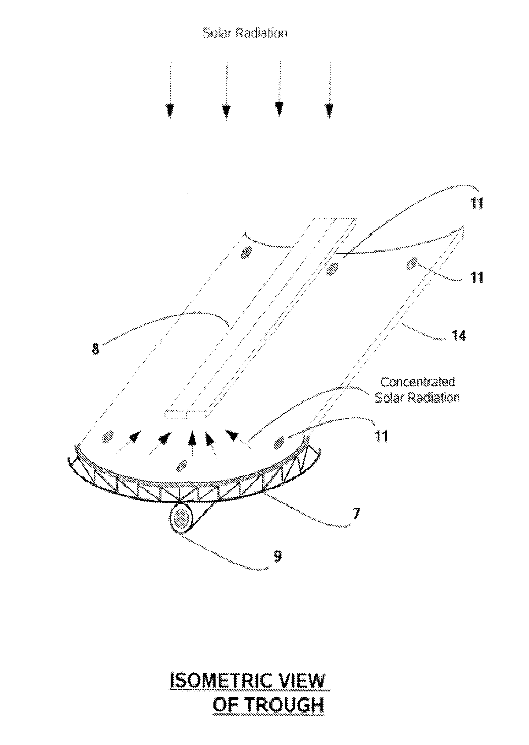
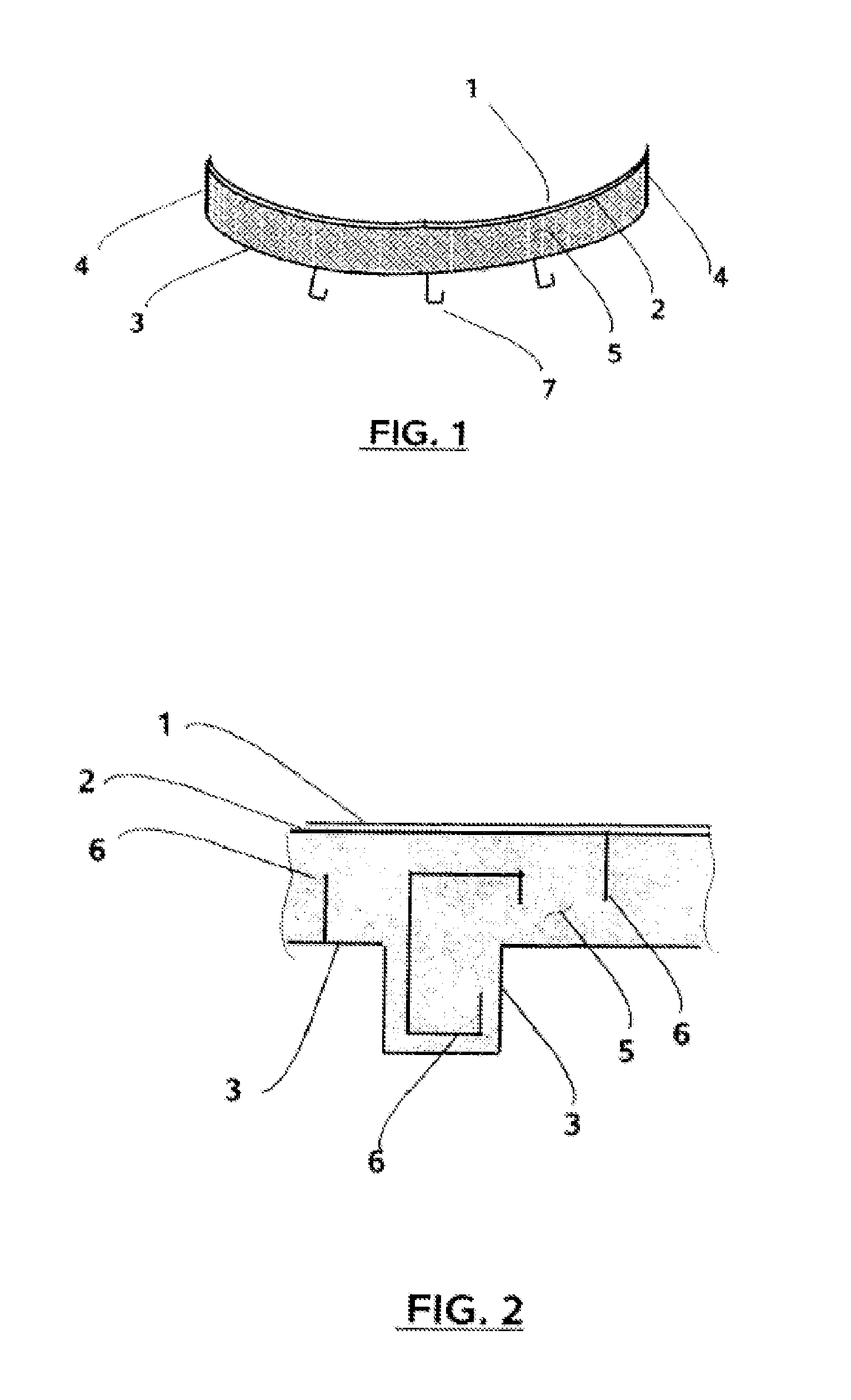
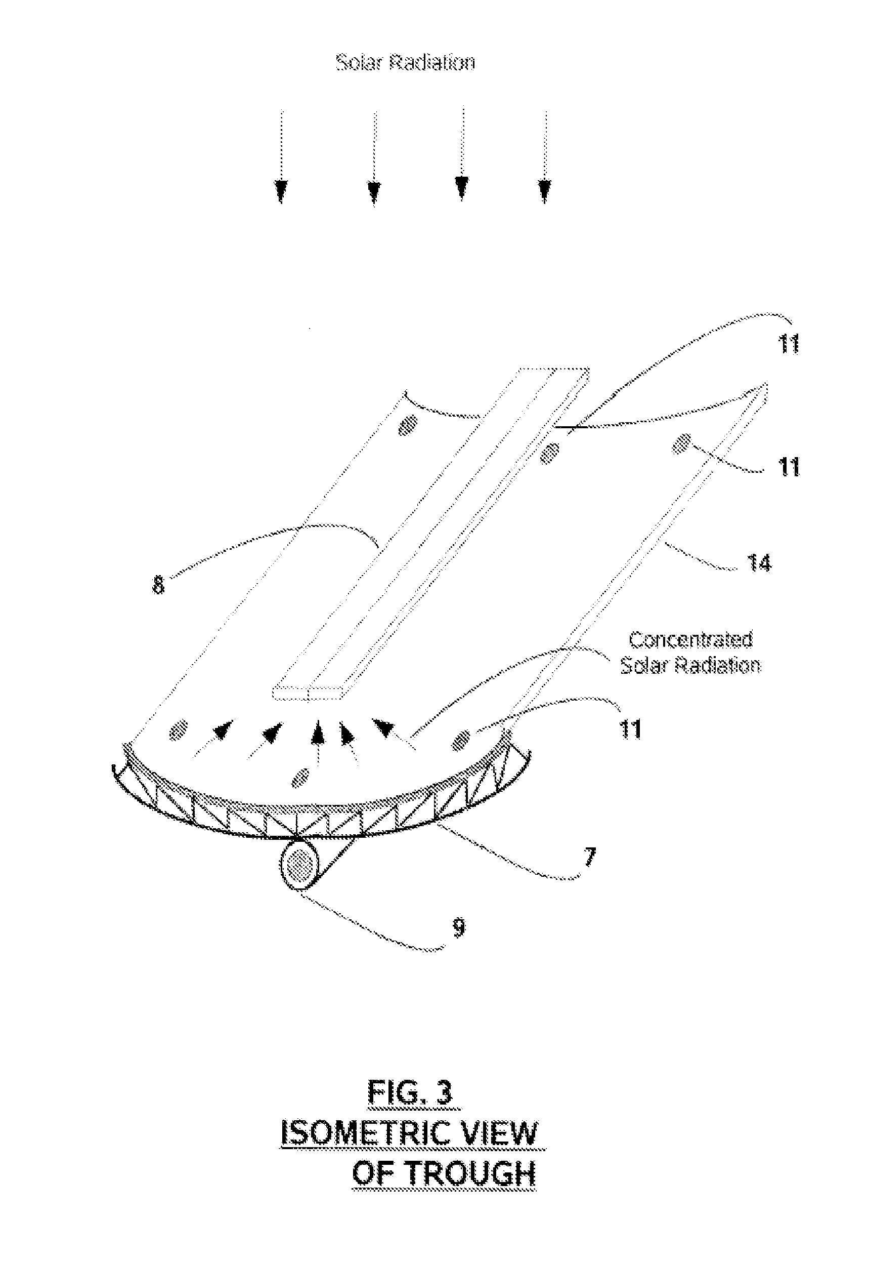
[0023]FIG. 1 shows a cross sectional view of a solar trough mirror (14) shown in FIG. 3 and of a dish mirror (15) shown in FIG. 4 and FIG. 5. Solar concentrating mirrors like trough, dish or fresnel can be manufactured from fiber reinforced concrete (FRC) or glass fiber reinforced concrete (GFRC). The trough mirror (14) shown in FIG. 3 consists of casing top (2), casing bottom (3), casing sides (4) and structural reinforcements (6). FRC or GFRC is injected through one or more injection p...


PUM

PropertyMeasurementUnit
Shapeaaaaaaaaaa
Adhesivityaaaaaaaaaa
Areaaaaaaaaaaa

Abstract

A building integrated solar mirror for use in a concentrated solar power (CSP) and concentrated photovoltaic (CPV) apparatus comprising a casing filled with fiber reinforced concrete having a reflective film attached to the concave curvature of the said casing, a process for its manufacture and use. The solar mirror characterized in that it forms an integral part of a building and can serve as roof or wall of the building, thus reducing the overall cost of transportation and installation of the said solar mirrors in CSP and CPV systems and also saving the enormous land required for the installation of these systems.

Description

FIELD OF THE INVENTION[0001]The invention relates to solar mirror, especially a building integrated solar mirror made of fiber reinforced concrete (FRC) or glass fiber reinforced concrete or a combination thereof for use in a concentrated solar systems and the process for its manufacture and use.BACKGROUND OF THE INVENTION[0002]Concentrated solar power system (CSP) and concentrated photovoltaic systems (CPV) provide an efficient means of utilizing the non-conventional energy resources but they are capital intensive and therefore not currently widely deployed. The successful commercialization of solar thermal energy largely depends upon developing a system that provides energy at a cost low enough to be competitive with energy from conventional fuels.[0003]Recent studies have shown that the majority of cost for a CPV or CSP system is represented by the concentrator (i.e mirrors).Another factor contributing to cost of these systems is their requirement for fair amount of land for thei...

Claims


Application Information

Patent Timeline
IPC IPC(8): G02B19/00
CPCG02B19/0042F24S20/67F24S23/71F24S23/74F24S23/80F24S23/82F24S2080/09Y02B10/20Y02E10/40Y02E10/44
Inventor THARISAYI, GEORGE PHILIP
Owner THARISAYI GEORGE PHILIP
Learn More