
Search Coil Assembly and System for Metal Detection

a technology of metal detection and search coil, which is applied in the direction of material analysis, measurement devices, instruments, etc., can solve the problems of difficult detection, difficult to determine the location of demining teams, and traditional techniques that are not per

Inactive Publication Date: 2013-11-21
NEL LOUIS MARLO
View PDF12 Cites 6 Cited by
  • Summary
  • Abstract
  • Description
  • Claims
  • Application Information

AI Technical Summary

Benefits of technology

The present invention relates to metal detection devices, particularly for detecting elongated objects such as landmines. The invention provides a search coil assembly that includes a search coil and a receive coil for detecting the presence and location of metal objects. The search coil has a unique design that allows for improved detection of elongated objects. The invention also includes a method for detecting the presence of tripwires, which are often difficult to detect and determine the location of. The technical effects of the invention include improved detection of elongated objects and better identification of the location of tripwires.

Problems solved by technology

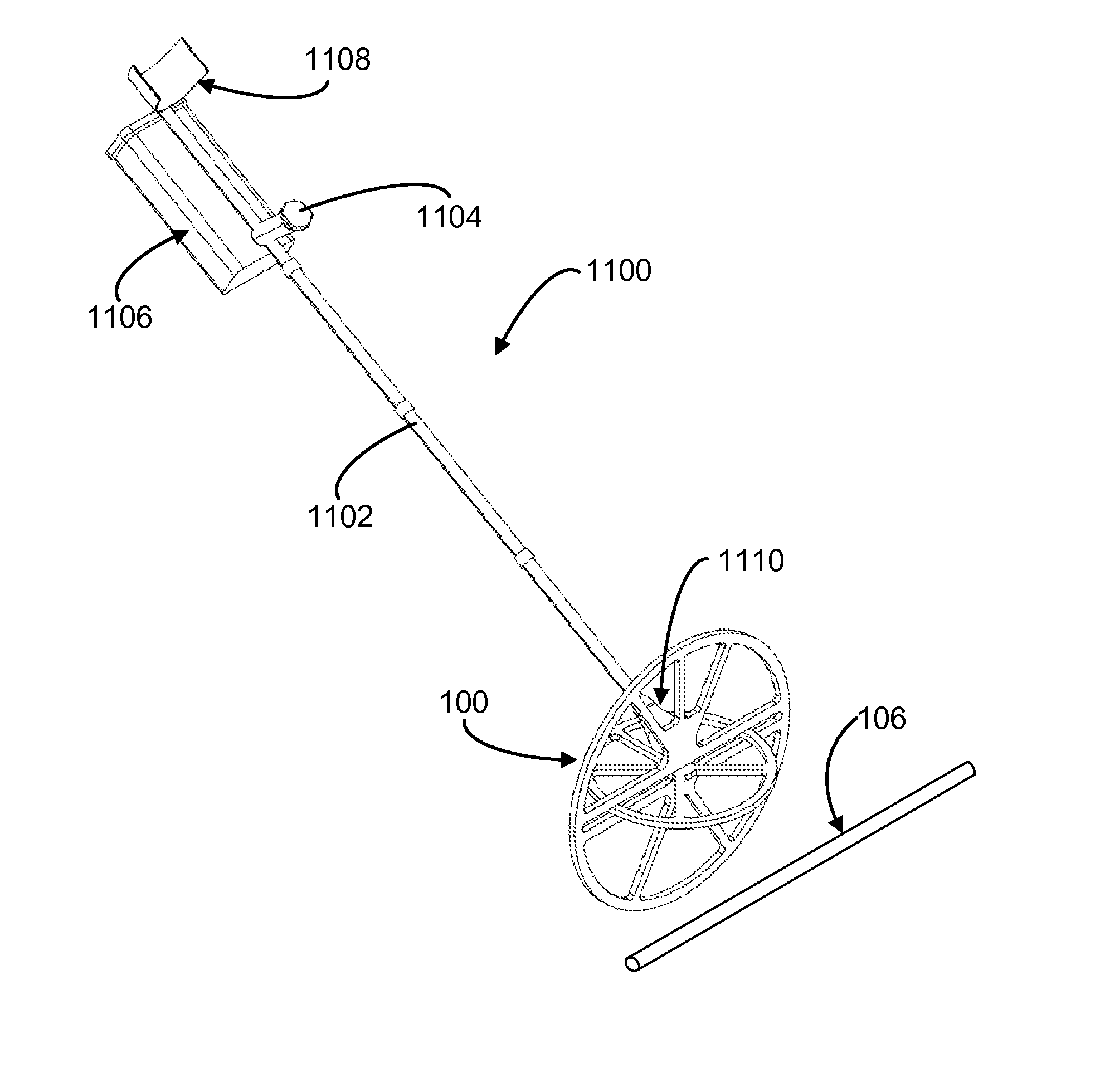
Elongated objects which have a small cross sectional areas and minimal metallic content, in particular landmine tripwires, are often difficult to detect and to determine the location of De-mining teams face considerable danger when trying to locate tripwire activated landmine wires, as the tripwires are typically located above the ground and may be obscured from vision by foliage.
In view of the foregoing, it is clear that these traditional techniques are not perfect and leave room for more optimal approaches.

Method used


Image

  • Search Coil Assembly and System for Metal Detection
  • Search Coil Assembly and System for Metal Detection
  • Search Coil Assembly and System for Metal Detection

Examples


Embodiment Construction

[0030]Embodiments of the present invention are best understood by reference to the detailed figures and description set forth herein.

[0031]Embodiments of the invention are discussed below with reference to the Figures. However, those skilled in the art will readily appreciate that the detailed description given herein with respect to these figures is for explanatory purposes as the invention extends beyond these limited embodiments. For example, it should be appreciated that those skilled in the art will, in light of the teachings of the present invention, recognize a multiplicity of alternate and suitable approaches, depending upon the needs of the particular application, to implement the functionality of any given detail described herein, beyond the particular implementation choices in the following embodiments described and shown. That is, there are numerous modifications and variations of the invention that are too numerous to be listed but that all fit within the scope of the i...


PUM

PropertyMeasurementUnit
angleaaaaaaaaaa
magnetic fieldaaaaaaaaaa
magneticaaaaaaaaaa

Abstract

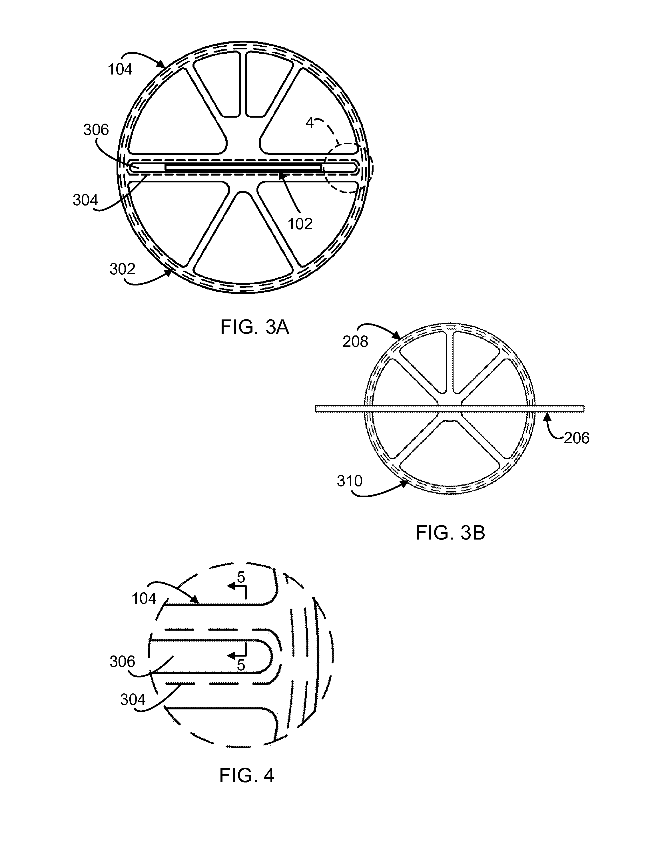
A search coil assembly comprises a transmit coil operable for radiating a magnetic field in response to a time varying current. The transmit coil comprises a conductive path being disposed at least within a transmit plane for radiating the magnetic field. At least one receive coil is operable for inducting a current in response to a time varying magnetic field. The receive coil comprises a conductive path being disposed within a receive plane for inducting the current. The receive coil is positionable to place the receive plane and the transmit plane in a substantially orthogonal orientation with the receive plane being substantially within null regions of the transmit coil's magnetic field, in which a metallic object, at a distance from the search coil assembly, reacts to a radiated magnetic field from the transmit coil, and the receive coil inducts a current in response to the reaction.

Description

FEDERALLY SPONSORED RESEARCH OR DEVELOPMENT[0001]Not applicable.REFERENCE TO SEQUENCE LISTING, A TABLE, OR A COMPUTER LISTING APPENDIX[0002]Not applicable.COPYRIGHT NOTICE[0003]A portion of the disclosure of this patent document contains material that is subject to copyright protection. The copyright owner has no objection to the facsimile reproduction by anyone of the patent document or patent disclosure as it appears in the Patent and Trademark Office, patent file or records, but otherwise reserves all copyright rights whatsoever.FIELD OF THE INVENTION[0004]One or more embodiments of the invention generally relate to metal detection devices. More particularly, one or more embodiments of the invention relate to metal detection devices for detecting elongated as well as non-elongated objects.BACKGROUND OF THE INVENTION[0005]The following background information may present examples of specific aspects of the prior art (e.g., without limitation, approaches, facts, or common wisdom) th...

Claims


Application Information

Patent Timeline
Patent Type & Authority Applications(United States)
IPC IPC(8): G01N27/72
CPCG01N27/902
Inventor NEL, LOUIS MARLO
Owner NEL LOUIS MARLO
Learn More