Kinematic-state encoder with magnetic sensor and target object

a technology of kinematic state and encoder, which is applied in the direction of speed/acceleration/shock measurement, measurement devices, instruments, etc., can solve problems such as errors increasing, and achieve the effects of increasing air gap, and reducing errors in the sensed relative kinematic sta

Active Publication Date: 2013-11-21
AB SKF
View PDF14 Cites 3 Cited by
  • Summary
  • Abstract
  • Description
  • Claims
  • Application Information

AI Technical Summary

Benefits of technology

The patent describes an apparatus for building target objects using interlocking segments. These segments can be easily positioned accurately with respect to each other due to the shape of their engaging interfaces. The use of multiple segments allows for the creation of target objects of different sizes, shapes, and material capabilities. Additionally, the apparatus includes a mechanism for accurately detecting the relative position and movement of the segments. The interlocking segments are shaped uniformly, which further enhances the advantages of the modular approach. The technical effects of this patent include improved precision and flexibility in target object design and construction.

Problems solved by technology

The error increases with increasing air gap at the boundary between two segments, and decreases with the surface area of the segments at their air gap.

Method used


Image

  • Kinematic-state encoder with magnetic sensor and target object
  • Kinematic-state encoder with magnetic sensor and target object
  • Kinematic-state encoder with magnetic sensor and target object

Examples


Embodiment Construction

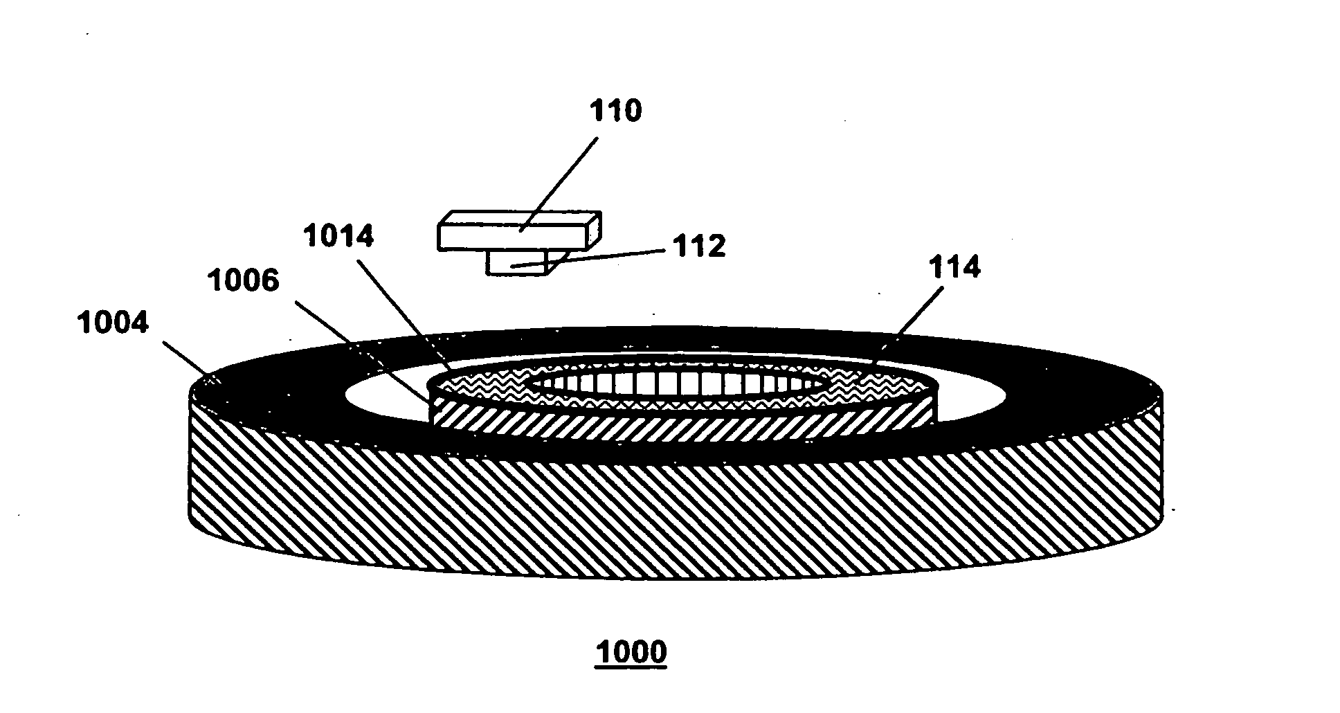
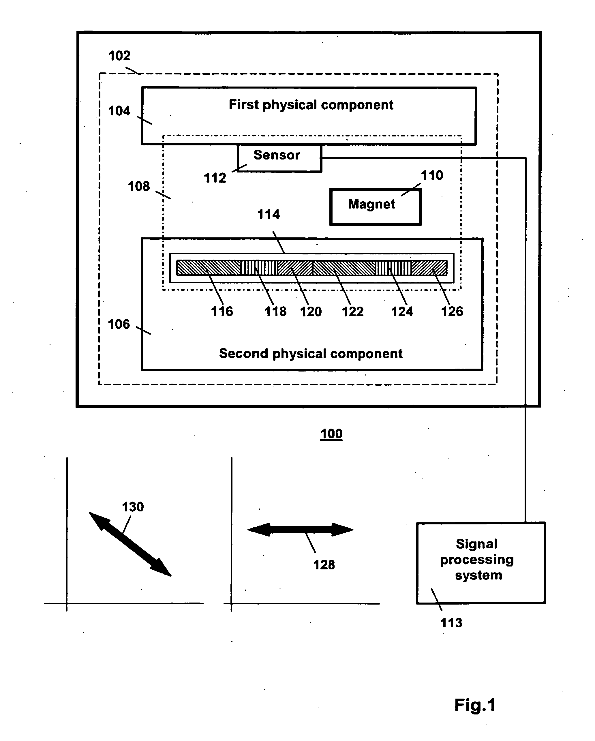
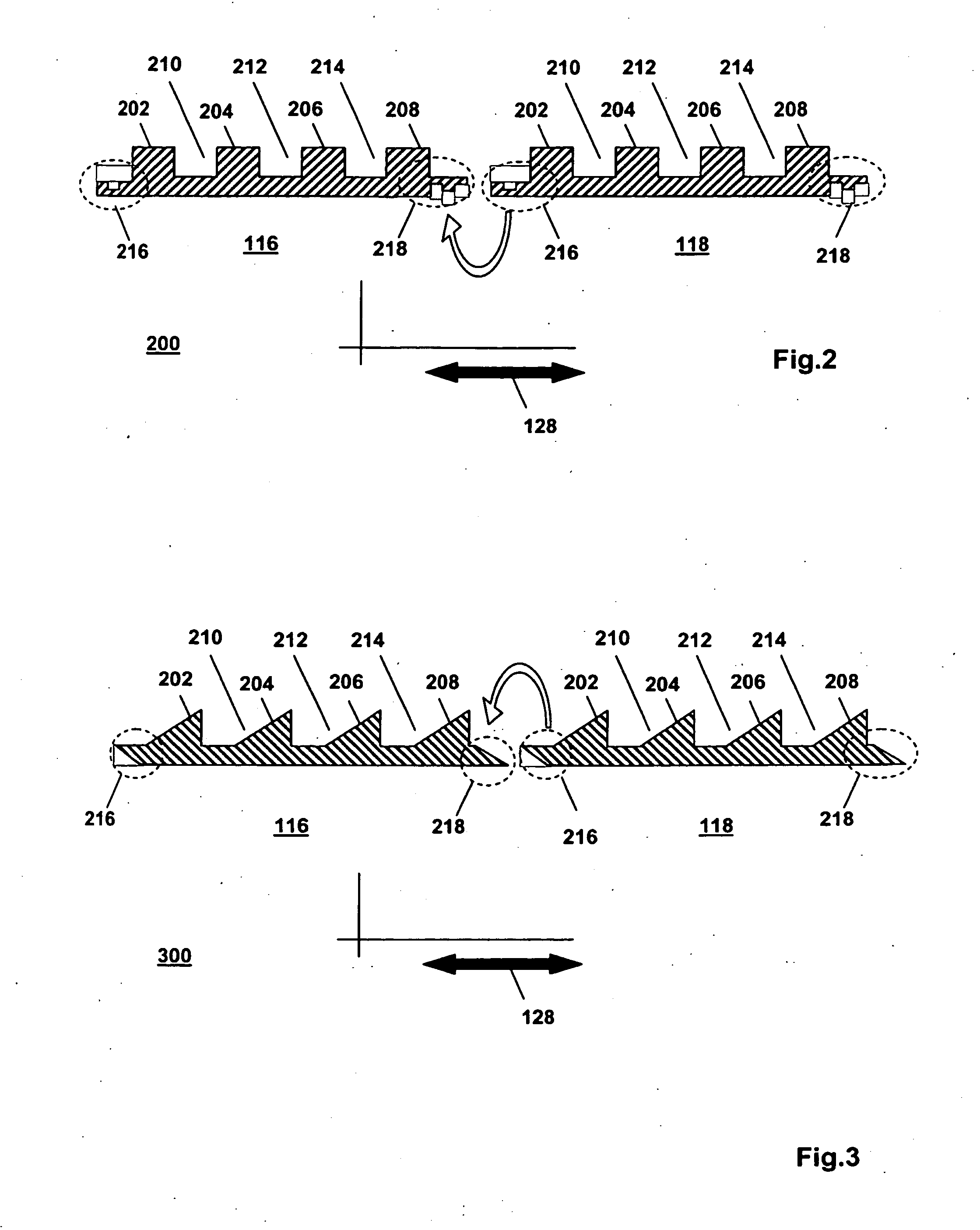
[0036]FIG. 1 is a block diagram of a first apparatus 100 in the invention. The first apparatus 100 is, e.g., a machine. The first apparatus 100 comprises a system 102 that has a first physical component 104, a second physical component 106 and a sensor arrangement 108. The first physical component 104 and the second physical component 106 are configured for moving relative to one another. The sensor arrangement 108 is configured for sensing a relative kinematic state of the first physical component 104 and the second physical component 106. The sensor arrangement 108 comprises a magnet 110 and a sensor 112. The sensor 112 is operative to generate a sensor signal indicative of a property of a magnetic field, generated by the magnet 110 and sensed at a location of the sensor 112. For example, the property sensed by the sensor 112 is an orientation of a magnetic field vector relative to the sensor 112 and / or the strength of the magnetic field vector, or the strength of a specific compo...


PUM


Abstract

An apparatus (1000) comprises a first physical component (1004), a second physical component (1006) and a sensor arrangement. The first and second physical components move relative to one another in operational use of the apparatus. The sensor arrangement senses a relative kinematic state of the first and second physical components. The sensor arrangement comprises a magnet (110) and a sensor (112). The sensor senses a property of a magnetic field of the magnet at a location of the sensor. The sensor is mounted stationary with respect to the first physical component. The sensor arrangement comprises a target object (114), mounted stationary with respect to the second physical component. The target object is configured for affecting an attribute of the property in dependence on the relative kinematic state. According to the invention target object (114) comprises a plurality of interlocking, segments.

Description

FIELD OF THE INVENTION[0001]The invention relates to an apparatus comprising a system with a first physical component, a second physical component and a sensor arrangement configured for sensing a relative kinematic state of the first and second physical components. The invention further relates to a system for use in such an apparatus, to a sensor arrangement for use in such an apparatus, to a target object for use in the sensor arrangement, and to a segment for use in the target object.BACKGROUND ART[0002]The following terminology is used in this text. The expression “kinematic state of a physical component” refers to the position, and / or velocity, and / or acceleration of the physical component with respect to some pre-determined reference system. The expression “relative kinematic state of two physical components” refers to the position, and / or velocity and / or acceleration of the physical components relative to each other. The expression “kinematic quantity” is used in this text t...

Claims


Application Information

Patent Timeline
IPC IPC(8): G01P3/487
CPCG01P3/487G01D5/145G01D5/2013G01D5/245G01D5/147
Inventor MOL, HENDRIK ANNE
Owner AB SKF
Why Eureka
Try Eureka