
Trajectory planning

a technology of trajectory planning and tracking, applied in the direction of educational models, navigation instruments, instruments, etc., can solve problems such as feature motion that cannot be achieved by conventional wheeled or tracked vehicles

Inactive Publication Date: 2013-11-14
BAE SYSTEMS PLC
View PDF0 Cites 10 Cited by
  • Summary
  • Abstract
  • Description
  • Claims
  • Application Information

AI Technical Summary

Benefits of technology

The present invention provides a method for determining a trajectory for a vehicle by identifying a starting position and a desired terminal position, and using a linear approximation to approximate the dynamics of the vehicle. The linear approximation is constrained by requirements that the acceleration of the vehicle is relatively large in a direction perpendicular to the velocity of the vehicle, and the acceleration is relatively small in a direction parallel to the velocity of the vehicle. The invention also includes constraints that the vehicle may not travel in a given region, and that the acceleration of the vehicle is less than a threshold value. The invention provides a more accurate and efficient method for determining a vehicle's trajectory.

Problems solved by technology

As a result, a determined trajectory may feature motion that cannot be achieved by conventional wheeled or tracked vehicles.

Method used


Image

  • Trajectory planning
  • Trajectory planning
  • Trajectory planning

Examples


Embodiment Construction

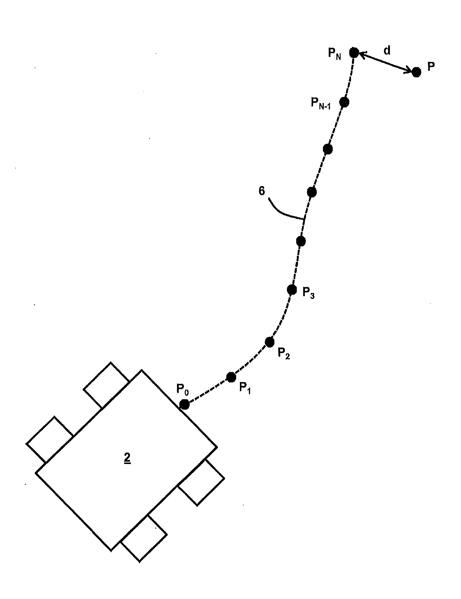
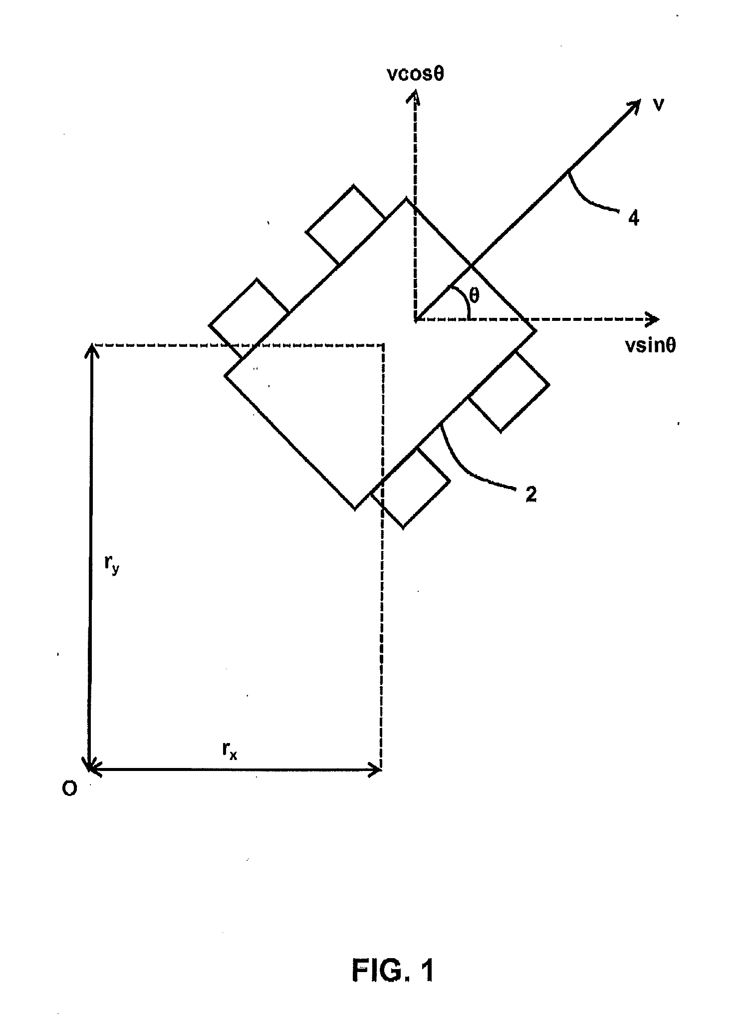
[0061]FIG. 1 is a schematic illustration (not to scale) of a land based vehicle, hereinafter referred to as “the vehicle 2”, for which an embodiment of a trajectory planner (not shown) plans a trajectory. The terminology “trajectory” is used herein to refer to a route of the vehicle from a first position to a second position.

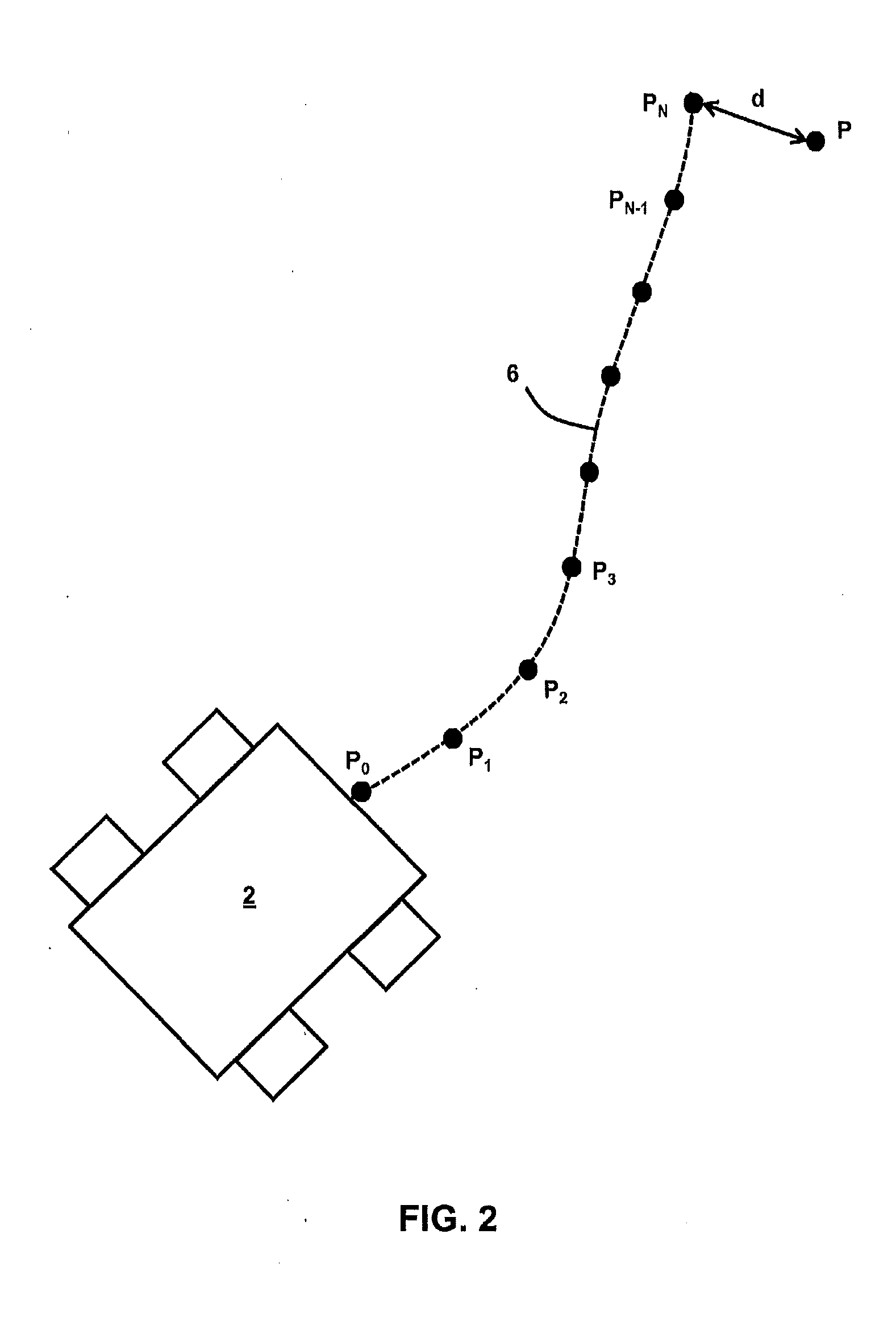
[0062]The following information about a state and operation of the vehicle 2, described with reference to FIG. 1 and FIG. 2, will be useful in understanding the embodiment described later below.

[0063]The vehicle 2 has the following state vector x:

x=(rxryθ)

where:[0064]rx is a distance of the vehicle 2 from an origin ◯ in the x-direction, as indicated in FIG. 1;[0065]ry is a distance of the vehicle 2 from the origin ◯ in the y-direction, as indicated in FIG. 1; and[0066]θ is an angle between the x-axis and a heading of the vehicle, hereinafter referred to as “the heading” and indicated in FIG. 1 by a solid arrow and the reference numeral 4.

[0067]Also,

x.=(vsinθvcos...


PUM


Abstract

A method and apparatus for determining a trajectory for a vehicle are disclosed, wherein, the method includes: identifying a starting position (p0) and a desired terminal position (P) for the vehicle; linearly approximating dynamics of the vehicle; and using the starting position (p0), desired terminal position (P), and linear approximation, determining the trajectory for the vehicle. The linear approximation can be constrained by requirements (e.g., specifications) that: (i) an acceleration applied to the vehicle at a point on the trajectory is relatively large when the acceleration acts in a direction that is substantially perpendicular to the velocity of the vehicle; and (ii) an acceleration applied to the vehicle at a point on the trajectory is relatively small when the acceleration acts in a direction that is substantially parallel to the velocity of the vehicle. The vehicle may have a curvature limit.

Description

FIELD OF THE INVENTION[0001]The present invention relates to trajectory planning and apparatus for the planning of trajectories for vehicles.BACKGROUND[0002]Trajectory planning methodologies, for example using Mixed Integer Linear Programming (MILP), are used to determine globally optimal trajectories for vehicles. Many trajectory planning methodologies constrain vehicle trajectories with a linear approximation of the vehicle's dynamics.[0003]Typically, a linear approximation of the vehicle's dynamics does not contain a notion of vehicle heading. This is typically because the introduction of a heading angle introduces non-linearities. As a result, a determined trajectory may feature motion that cannot be achieved by conventional wheeled or tracked vehicles.SUMMARY OF THE INVENTION[0004]In a first aspect, the present invention provides a method for determining a trajectory for a vehicle, the method comprising: identifying a starting position for the vehicle; identifying a desired ter...

Claims


Application Information

Patent Timeline
IPC IPC(8): G01C21/00
CPCG01C21/00G05D1/0212G09B23/10
Inventor MATHEWS, GEORGE MORGANDEITTERT, MARKUSRICHARDS, ARTHUR GEORGE
Owner BAE SYSTEMS PLC
Learn More