Shaped charge tubing cutter

a technology of shaped charge and cutter, which is applied in the direction of instruments, sealing/packing, and wellbore/well accessories, etc., can solve the problems of unconfined explosives simply outgasing and burning, high explosives compressed, and greater difficulty in detonation, so as to prevent moisture migration. , the effect of preventing the migration of moistur

Active Publication Date: 2013-11-14
W T BELL INT INC
View PDF3 Cites 30 Cited by
  • Summary
  • Abstract
  • Description
  • Claims
  • Application Information

AI Technical Summary

Benefits of technology

The invention features a design that prevents the detonation wave from causing damage to the cutter explosive. It also includes a fluid seal element to prevent moisture from entering the cutter housing. These features enhance the reliability and performance of the invention.

Problems solved by technology

However, another characteristic of densely compressed high explosives is a greater difficulty to detonate.
Larger boosters, for more densely compressed explosives, introduce other complications to the downhole tubing cutter design.
If heated, an unconfined explosive will simply out-gas and burn.
If the explosive is confined, however, the gas may develop sufficient pressure to initiate a detonation.
Unfortunately, the environmental circumstances of a drilling rig floor, which is where final cutter assembly must occur, are often hostile and usually not conducive to the attentive care required for final assembly of a high explosive tool.
As normally fabricated, however, there is an open channel space along the axis of the assembled unit.
This opportunity is exacerbated by rough or poorly machined seal surfaces.
Under a low pressure differential, a fluid tight seal is much more problematic if the seal surfaces are roughly machined or corrupted by deposits.
For explosive tools such as shaped charge cutters and perforators, such low pressure leakage may be disabling.
Curiously, in a deep well environment, a tool with a low pressure leak may ultimately acquire a complete seal as the tool descends into realms of greater pressure.

Method used


Image

  • Shaped charge tubing cutter
  • Shaped charge tubing cutter
  • Shaped charge tubing cutter

Examples


Embodiment Construction

[0044]As used herein, the terms “up” and “down”, “upper” and “lower”, “upwardly” and downwardly”, “upstream” and “downstream”; “above” and “below”; and other like terms indicating relative positions above or below a given point or element are used in this description to more clearly describe some embodiments of the invention. However, when applied to equipment and methods for use in wells that are deviated or horizontal, such terms may refer to a left to right, right to left, or other relationship as appropriate. Moreover, in the specification and appended claims, the terms “pipe”, “tube”, “tubular”, “casing”, “liner” and / or “other tubular goods” are to be interpreted and defined generically to mean any and all of such elements without limitation of industry usage.

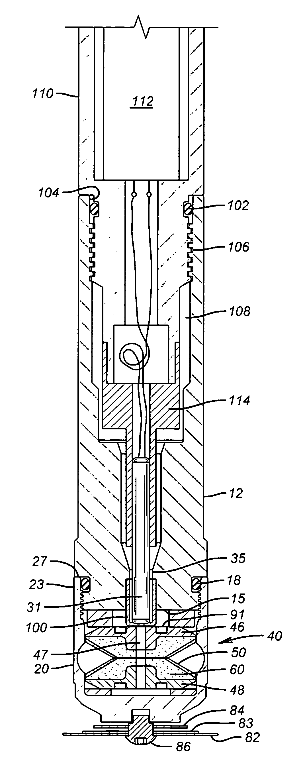
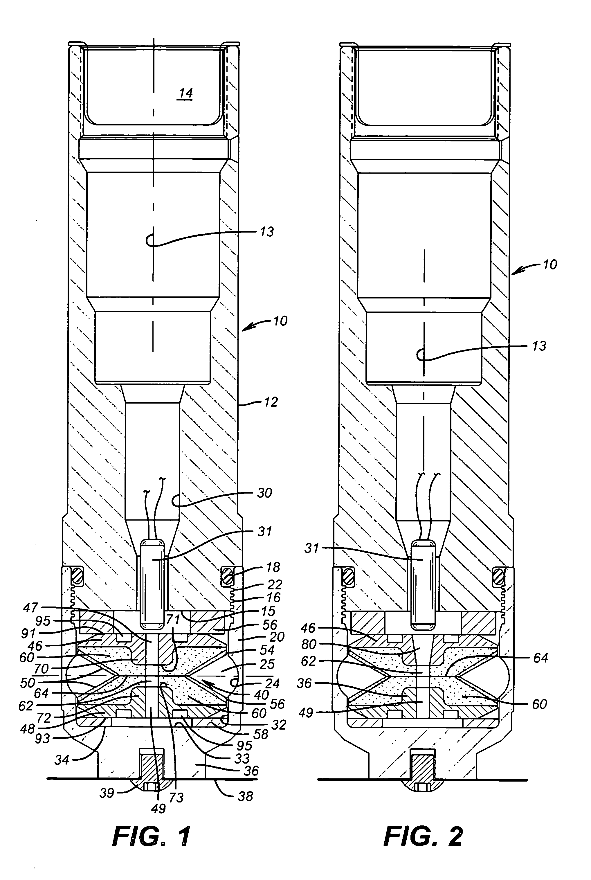
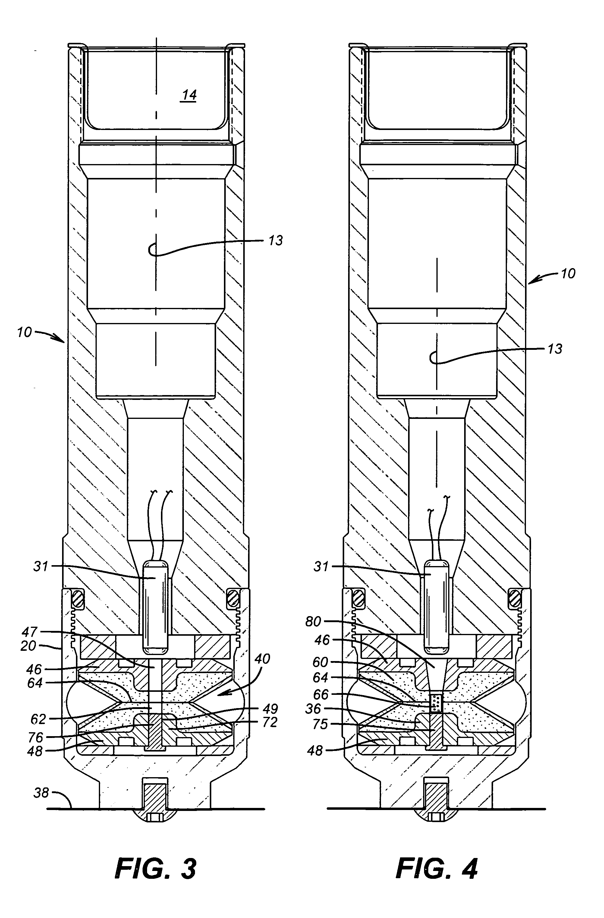
[0045]Referring initially to the invention embodiment of FIG. 1, the cutter assembly 10 comprises a top sub 12 having a threaded internal socket 14 that axially penetrates the “upper” end of the top sub. The socket thread ...


PUM


Abstract

A shaped charge pipe cutter is constructed with the cutter explosive material packed intimately around an axially elongated void space that is continued through a heavy wall boss portion of the upper thrust disc. The boss wall is continued to within a critical initiation distance of a half-cuter junction plane. An explosive detonator is positioned along the void space axis proximate of the outer plane of the upper thrust disc. Geometric configurations of the charge thrust disc and end-plate concentrate the detonation energy at the critical initiation zone.

Description

CROSS-REFERENCE TO RELATED APPLICATIONS[0001]Not ApplicableSTATEMENT REGARDING FEDERALLY SPONSORED RESEARCH OR DEVELOPMENT[0002]Not ApplicableBACKGROUND OF THE INVENTION[0003]1. Field of the Invention[0004]The present invention relates to shaped charge tools for explosively severing tubular goods including, but not limited to, pipe, tube, casing and / or casing liner.[0005]2. Description of Related Art[0006]The capacity to quickly, reliably and cleanly sever a joint of tubing or casing deeply within a wellbore is an essential maintenance and salvage operation in the petroleum drilling and exploration industry. Generally, the industry relies upon mechanical, chemical or pyrotechnic devices for such cutting. Among the available options, shaped charge (SC) explosive cutters are often the simplest, fastest and least expensive tools for cutting pipe in a well. The devices are typically conveyed into a well for detonation on a wireline or length of coiled tubing.[0007]Typical explosive pipe...

Claims


Application Information

Patent Timeline
IPC IPC(8): E21B43/116G01N33/22E21B19/08E21B23/00F42B1/028E21B17/10
CPCF42B1/028E21B29/02F42D3/00F42B3/00E21B43/117F42B3/22
Inventor BELL, WILLIAM T.RAIRIGH, JAMES G.
Owner W T BELL INT INC
Why Eureka
Try Eureka