Scroll shape of centrifugal compressor

a centrifugal compressor and scrolling technology, applied in the direction of machines/engines, stators, liquid fuel engines, etc., can solve the problems of difficult to accurately determine flow rate and velocity, difficult and reduced operating range, so as to maximize pressure recovery region and improve performance of centrifugal compressors , the ratio of the cross-sectional area of the scroll portion is constan

Active Publication Date: 2013-11-07
MITSUBISHI HEAVY IND LTD
View PDF3 Cites 11 Cited by
  • Summary
  • Abstract
  • Description
  • Claims
  • Application Information

AI Technical Summary

Benefits of technology

[0036]According to such a configuration, by determining a region that is not affected by separation of the fluid due to the tongue portion and maximizing the pressure recovery region in which fluid velocity is reduced, performance of the centrifugal compressor is improved.
[0037]In addition, in the present invention, favorably, a radius of a centroid of the cross section and a radius of a center of the scroll portion are varied while keeping the enlargement ratio of the cross-sectional area of the scroll portion constant in order to decrease the velocity of the fluid flowing through the scroll portion.
[0038]Furthermore, in the present invention, favorably, the radius of the centroid of the cross section of the scroll portion and a radius of a center of the scroll portion are kept constant while the enlargement rate of the cross-sectional area is varied in order to decrease the velocity of the fluid flowing through the scroll portion.
[0039]By gradually increasing the cross-sectional area of the scroll portion from the tongue portion to an arbitrary angle in a circumferential direction of the scroll portion and decreasing an enlargement rate of the cross-sectional area from the arbitrary angle to a winding end of the scroll portion, a portion in which a velocity of a flow of the fluid in the scroll is decreased and a portion in which the velocity of the flow of the fluid in the scroll is increased are created to ensure sufficient static pressure recovery and to produce high efficiency and high pressure as a centrifugal compressor.

Problems solved by technology

When a fluid flowing out from a compressor has velocity, since dynamic pressure increases but static pressure does not increase, pressure ratio and efficiency decline.
Although pressure is recovered by reducing the velocity of the fluid in the diffuser portion, the velocity of the fluid differs between an inner side and an outer side of the scroll in a cross section of each portion of the scroll portion, which makes it difficult to accurately determine flow rate and velocity.
In this case, due to constant decrease of velocity in a flow direction, a boundary layer between the fluid and a wall surface of the scroll portion increases and prevents sufficient static pressure recovery, and an occurrence of surging results in defects such as a reduction in an operating range and a decline in turbocharging efficiency.

Method used


Image

  • Scroll shape of centrifugal compressor
  • Scroll shape of centrifugal compressor
  • Scroll shape of centrifugal compressor

Examples


first embodiment

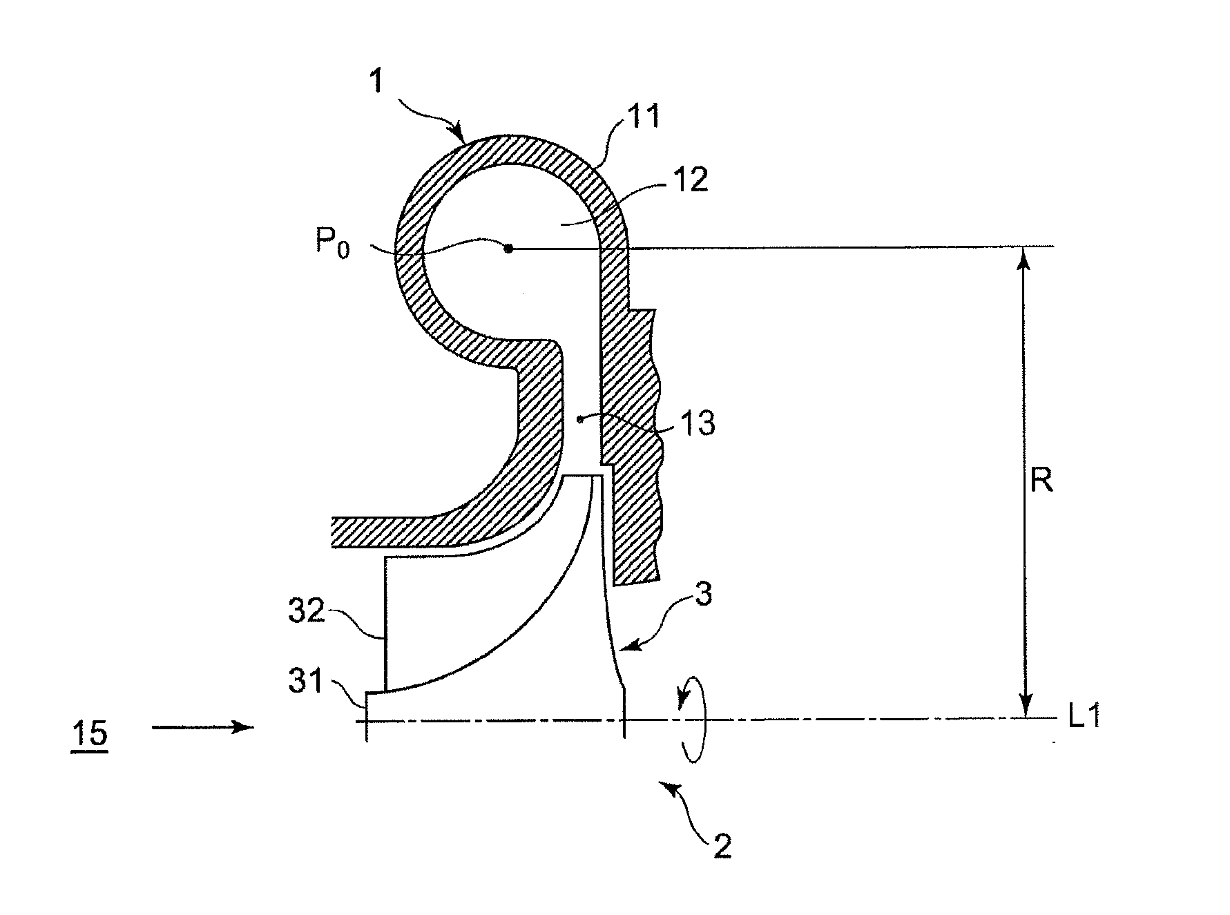
[0051]As shown in FIG. 7, a scroll according to the present invention comprises a fluid flow path constituted by a diffuser portion 13 which forms a roughly donut shape on an outer circumferential side of a compressor impeller 3 and which enables recovery of static pressure by decreasing the velocity of fluid (gas) that is discharged from the compressor impeller 3, a scroll portion 12 which is formed on an outer circumferential side of the diffuser portion 13 so that a cross-sectional area of the scroll portion 12 spirally increases in a winding direction (a flowing direction of the fluid) and which decreases velocity and increases pressure of the fluid, and an outlet tube (not shown).

[0052]When the compressor impeller 3 rotates, centrifugal vanes 32 compress a fluid such as a gas or air introduced from an air passageway 15. A flow of the fluid (gas) formed in this manner proceeds from an outer circumferential end of the compressor impeller 3, passes through the diffuser portion 13 ...

second embodiment

[0086]The present embodiment will be described with reference to FIG. 4.

[0087]Moreover, in the present embodiment, since a basic shape is the same as that of the first embodiment with the sole exception of the shape of the scroll portion 12 which forms a flow path of a fluid such as gas or air discharged from the diffuser portion 13 that is arranged on a downstream side of the compressor impeller 3 of a centrifugal compressor, only the scroll portion 12 will be described and descriptions of other components will be omitted.

[0088]Moreover, the same terms will be denoted by the same reference characters and descriptions thereof will be omitted.

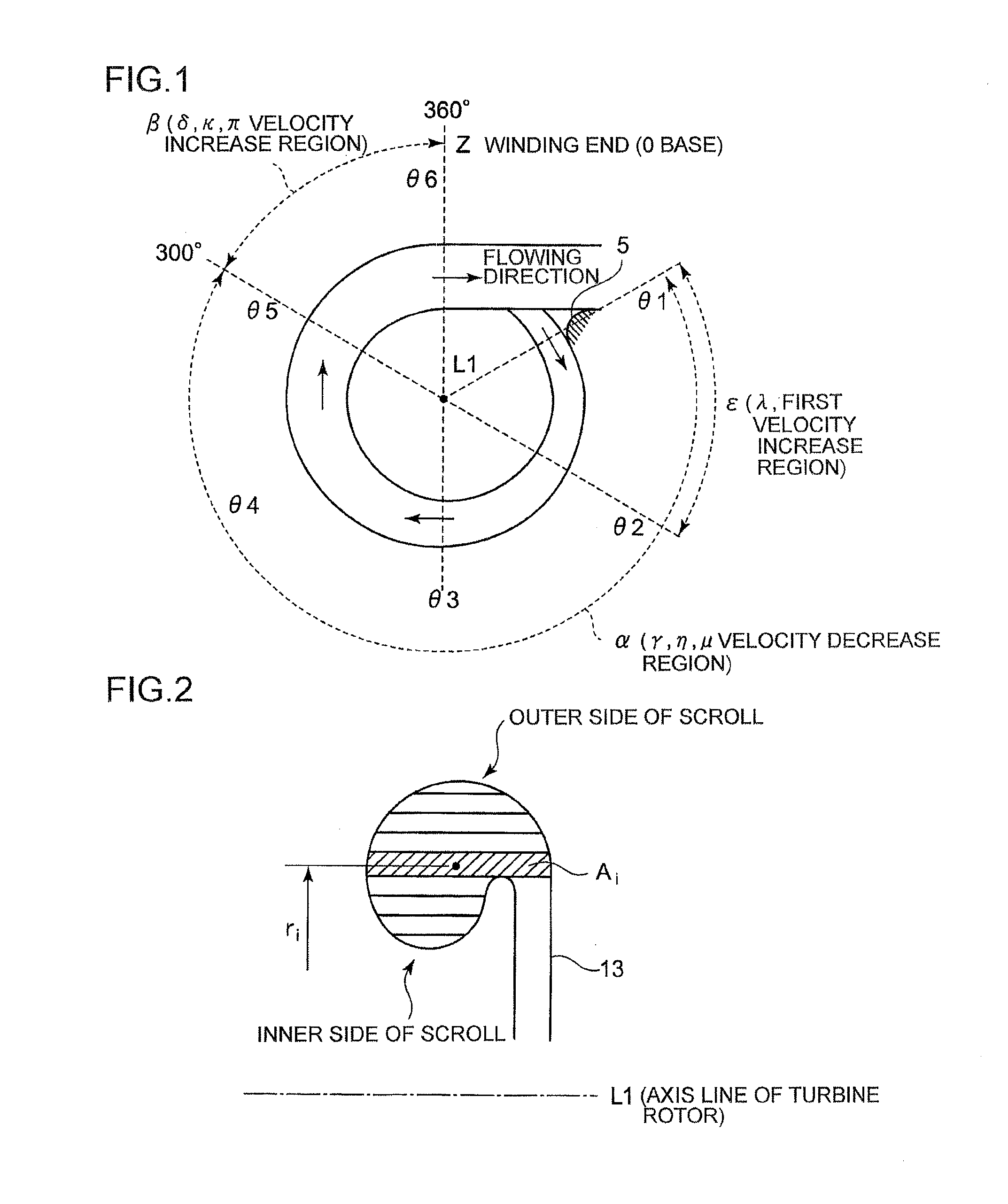
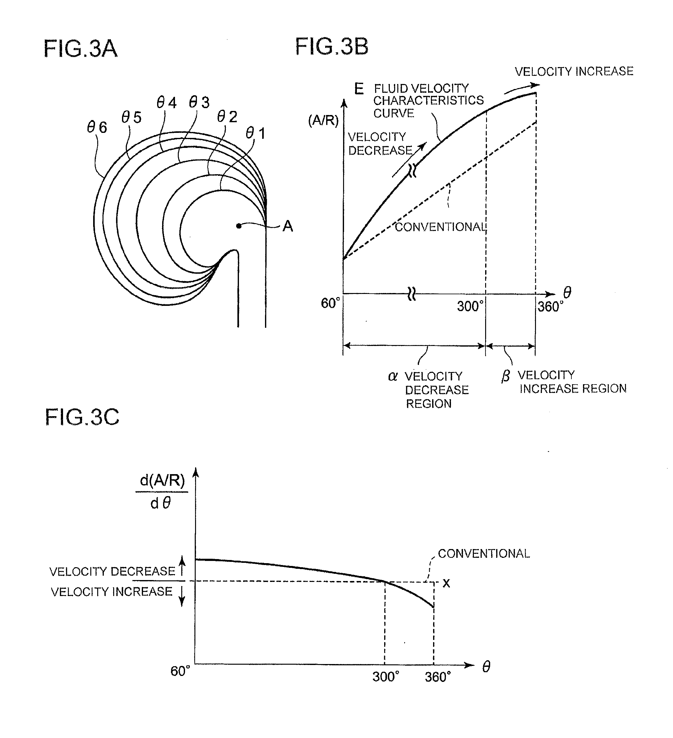
[0089]FIG. 4A is a sectional view displaying cross sections of the scroll portion at respective portions θ1, θ2, θ3, θ4, θ5, and θ6 in a winding direction of the scroll (the flowing direction of the fluid) shown in FIG. 1 laminated on top of each other according to the present embodiment. FIG. 4A represents a case where a centroid radius R of A / ...

third embodiment

[0100]The present embodiment will be described with reference to FIG. 5.

[0101]Moreover, in the present embodiment, since a basic shape is the same as that of the first embodiment with the sole exception of the shape of the scroll portion 12 of a centrifugal compressor which forms a flow path of a fluid such as gas or air projected from a diffuser portion arranged on a downstream side of a compressor impeller of the centrifugal compressor, only the scroll portion 12 will be described and descriptions of other components will be omitted.

[0102]Moreover, the same terms will be denoted by the same reference characters and descriptions thereof will be omitted.

[0103]FIG. 5A is a sectional view displaying cross sections of the scroll portion at respective portions in a winding direction of the scroll (the flowing direction of the fluid) laminated on top of each other according to the present embodiment. FIG. 5A shows the lamination of cross sections of respective portions θ1, θ2, θ3, θ4, θ5...


PUM


Abstract

In a scroll shape of a centrifugal compressor, an enlargement rate of a ratio A/R of a cross-sectional area A of a scroll portion 12 to a radius R from an axis L1 of a compressor impeller 3 to a centroid P0 of a cross section of the scroll portion is reduced from a winding start to a winding end of the scroll portion.

Description

TECHNICAL FIELD[0001]The present invention relates to a centrifugal compressor comprising a scroll portion which constitutes a flow path formed by rotation of a compressor impeller in a spiral shape in an outer peripheral portion of the compressor impeller, and to a scroll shape which enables recovery of static pressure of a fluid (gas) in the scroll portion.BACKGROUND ART[0002]Centrifugal compressors are required to have high pressure and high efficiency over a wide operating range.[0003]FIG. 7 shows an enlarged sectional view of a substantial part of an upper half of an axis of a rotary shaft of a compressor impeller in a centrifugal compressor.[0004]A compressor 1 of a centrifugal compressor mainly comprises a compressor impeller 3 constituted by a rotating hub 31 and a large number of centrifugal vanes 32 attached to an outer circumferential surface of the hub 31, a shaft 2 coupled to a rotary drive source of the compressor impeller 3, and a compressor housing 11 which houses th...

Claims


Application Information

Patent Timeline
Patent Type & Authority Applications(United States)
IPC IPC(8): F04D29/42
CPCF04D29/4206F04D29/441F04D29/681F05D2250/52F04D29/403F04D29/4226
Inventor TOMITA, ISAOSHIRAISHI, TAKASHIIWAKIRI, KENICHIRO
Owner MITSUBISHI HEAVY IND LTD
Why Eureka
Try Eureka