
Doll head having a magnetically adjustable facial contour and method of assembling same

a doll head and magnetic technology, applied in the field of doll heads, can solve the problems of static and immobile doll head facial features, static and immobile doll head facial expression, and inability to readily change to express joy, etc., and achieve the effect of reducing the number of static doll head designs

Active Publication Date: 2013-10-31
REALBOTIX LLC
View PDF15 Cites 25 Cited by
  • Summary
  • Abstract
  • Description
  • Claims
  • Application Information

AI Technical Summary

Benefits of technology

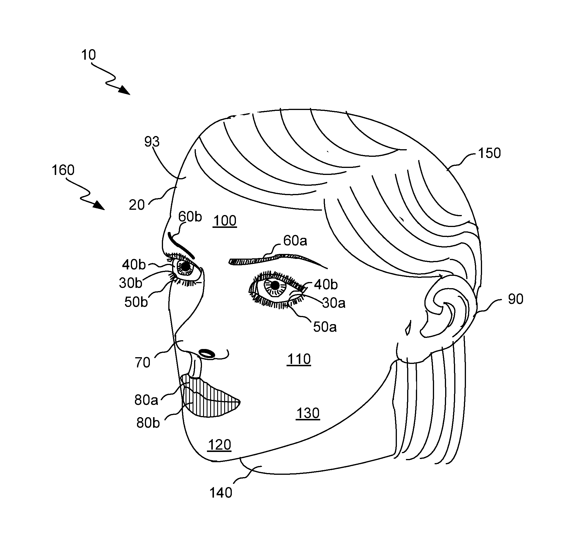
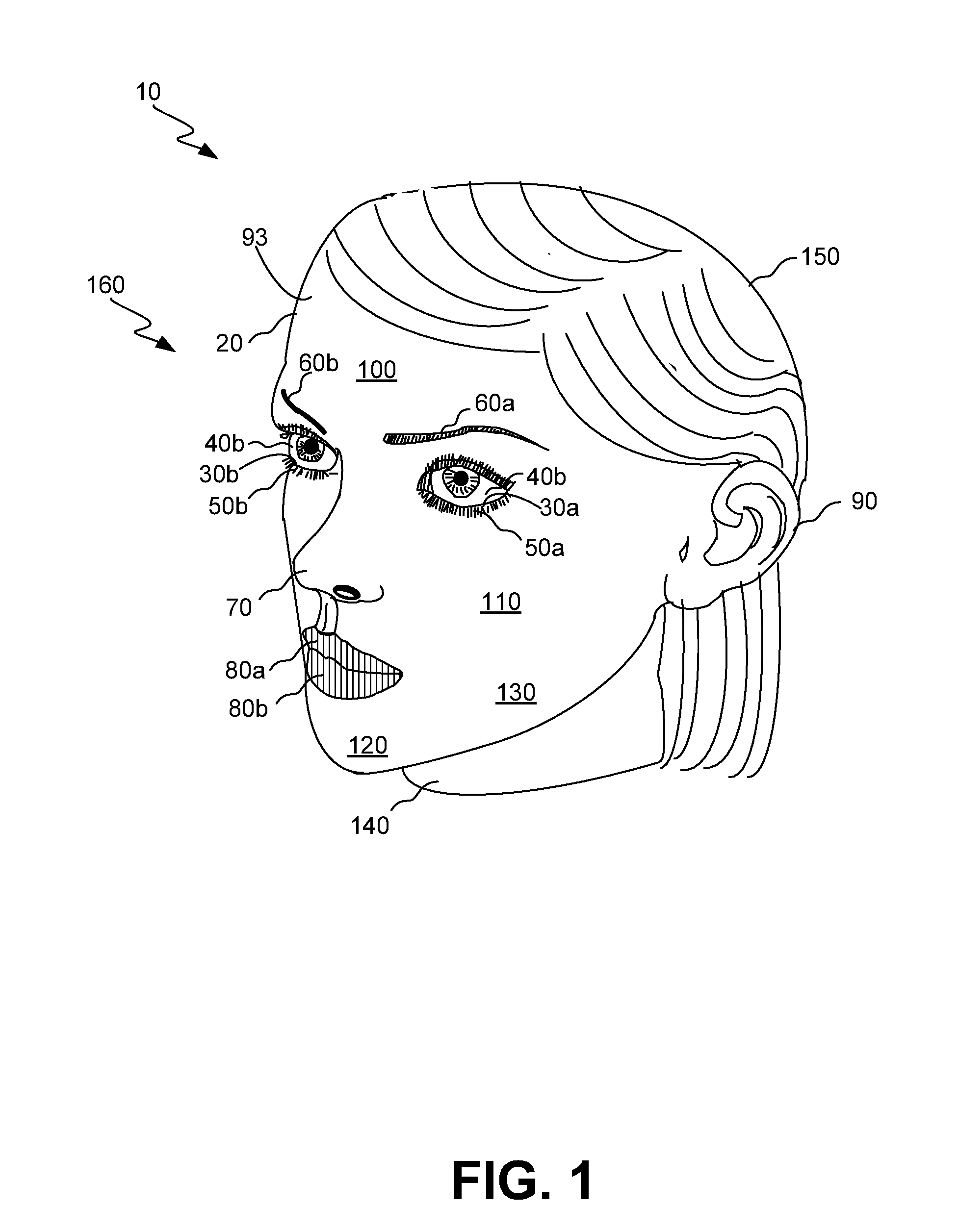
The present invention provides a doll head with a magnetically adjustable facial contour. The head includes a rigid face mask support and a flexible face mask that can be adjusted from a first facial contour to a second facial contour. The adjustment is achieved through the use of magnets that are magnetically coupled to each other, allowing for the movement of the face mask as the magnets are adjusted. The invention also includes a jaw assembly that can open and close the doll's mouth, and a mechanism for causing the eyes to wink. The technical effects of the invention include the ability to create a variety of facial contours with a single doll head and the use of magnetic means for the adjustment of the face mask.

Problems solved by technology

Often, however, the facial features of the doll head are static and immobile.
That is, the facial expression of the doll head is invariable and cannot readily change to express joy, surprise, amazement, confusion, anger, fear and other emotions.
Such static doll head designs rarely retain the user's interest.
However, these interchangeable parts are cumbersome and time-consuming to deploy because the parts must first be removed and then exchanged with other parts.
In addition, some prior art doll head designs do not suitably exhibit life-like attributes, such as realistic eye movement.
In addition, such a doll head cannot laterally move its eyes from side-to-side to simulate following an object or person moving, for example, across a room.
Absence of emotion and life-like movement detract from the user's enjoyment of the doll.
Moreover, such prior art dolls lack independently operable facial features.
In addition, such dolls lack an ability to dynamically contort or change a region of the doll's face independently of another region of the doll's face to simulate, for example, a smile or frown.
However, the expression evinced by each selected face mask or head is static and, thus, immobile.
However, the expression of each face member is static and, thus, immobile.
Although this approach discloses use of magnets, changes in the doll's facial expression is apparently only achieved by replacing lips, ears, wigs, eyebrows, eyes and noses.
However, this approach apparently only controls eye movement and does not address magnetically controlling movement of facial features.
Thus, although the doll's eye movement is controlled by use of a magnet, the doll's facial expression remains static and, thus, immobile.

Method used


Image

  • Doll head having a magnetically adjustable facial contour and method of assembling same
  • Doll head having a magnetically adjustable facial contour and method of assembling same
  • Doll head having a magnetically adjustable facial contour and method of assembling same

Examples


second embodiment

[0067]Referring again to FIG. 11, each of solenoids 610a / 610b will generate a magnetic field when solenoids 610a / 610b are electrically energized. The magnetic fields generated by solenoids 610a / 610b will act on respective ones of rods 560, such that, as carriage assembly 600 is moved either vertically and / or horizontally, rods 560 will move in bores 550 to a like extent because metal comprising rods 560 will respond to the magnetic field. Also, as previously mentioned, eye elements may be adapted to wink when an upper portion thereof is suitably painted or covered. Winking is accomplished by selectively energizing solenoids 610a / 610b. As rods 560 move, eye elements 40a / 40b will simultaneously move. In this manner, second embodiment adjustment mechanism 570 is adapted to controllably move eye elements 40a / 40b in their corresponding eye sockets 360a / 360b.

first embodiment

[0068]Returning to FIGS. 3, 4, 5 and 6, upper simulated gingival 490 belonging to previously mentioned jaw assembly 430 is adapted to pivot about pivot pin 525 for opening and closing jaw assembly 430. In this regard, a resilient member, such as a spring (not shown), may be interposed between upper simulated gingival 490 and lower simulated gingival 510 in a manner that closes jaw assembly 430 until jaw assembly 430 is acted upon by a magnetic field. The force of the magnetic field, which is generated by one of the first embodiment adjustment mechanisms 490 disposed near jaw assembly 430, is sufficiently strong to overcome the spring's tension in order to open jaw assembly 430 when desired. Alternatively, jaw assembly 430 may be mechanically operable by means of a spur gear 632, or other suitable means, that engages jaw assembly 430 to pivot upper simulated gingival 490. A reversible motor 635, that is powered by a battery 637, is connected to spur gear 632 for rotating spur gear 63...


PUM


Abstract

A doll head is disclosed having a magnetically adjustable facial contour, along with a method for assembling same. In one embodiment, the doll head includes a face mask support on which is mounted an elastically deformable face mask. Movable adjustment mechanisms and associated motors and power supplies for moving the adjustment mechanisms are disposed in the face mask support. Each adjustment mechanism generates an applied magnetic field. First magnets are affixed to an inner surface of the face mask, and second magnets in magnetic communication with the first magnets are slidably disposed on an exterior surface of the face mask support. The adjustment mechanisms selectively apply magnetic fields that slidably adjust position of the second magnets. As position of the second magnets slidably adjust, the first magnets move to a like extent. As the first magnets move, contour of the face mask adjusts to change expression of the doll head.

Description

FIELD OF THE INVENTION[0001]This invention generally relates to doll heads and more particularly relates to doll heads having an adjustable facial contour.BACKGROUND OF THE INVENTION[0002]Dolls have many uses, such as play toys for children, prizes at amusement parks, figures at religious ceremonies, mannequins in department stores, decoration in homes and businesses, anatomically correct figures to train doctors and nurses, collectors' items and other uses.[0003]A doll, such as in the form of a full-sized mannequin or smaller children's toy, will include a doll head. The doll head typically possesses features of a human or animal. Often, however, the facial features of the doll head are static and immobile. That is, the facial expression of the doll head is invariable and cannot readily change to express joy, surprise, amazement, confusion, anger, fear and other emotions. Such static doll head designs rarely retain the user's interest.[0004]In an effort to retain the user's interes...

Claims


Application Information

Patent Timeline
IPC IPC(8): A63H3/36
CPCA63H3/365A63H3/40
Inventor MCMULLEN, MATTHEW
Owner REALBOTIX LLC
Learn More