
Multi-contact connector socket for rapid fastening to a panel, and associated installation and removal methods

Active Publication Date: 2013-10-24
RADIALL SA
View PDF4 Cites 1 Cited by
  • Summary
  • Abstract
  • Description
  • Claims
  • Application Information

AI Technical Summary

Benefits of technology

The invention allows for quick and easy installation and removal of connector sockets on panels, which is useful in industrial settings where a large number of sockets need to be installed or removed on a single panel. The housing of the connector can be made as a single part, simplifying its fabrication and assembly process. Additionally, the connector doesn't require an insert with cells, which can save time and effort in the assembly process.

Problems solved by technology

Although presently-existing means for fastening a multi-contact connector to a panel are effective, in particular when subjected to high levels of mechanical stress, they present certain drawbacks, such as:relatively long periods of time are required for installation or removal;it is always necessary to use a tool; andremoval can be performed only from one face of the panel, either only from the front face, i.e. the side where a connection is made, or else only from the rear face, i.e. the side where the contacts extend in the socket.
In addition, a drawback with that adapter is that installing the clip and the shape and the dimensions of the hooks do not make it possible, for any given clip, to obtain fastening over a relatively large range of panel thicknesses.
Another major drawback is that the force holding the adapter to the panel as applied by the clip is weak, since it is directly associated with the intrinsic flexibility of the clip.
Such a weak holding force can be risky if severe mechanical stresses should arise, such as high levels of vibration or a large traction force on the connector.

Method used


Image

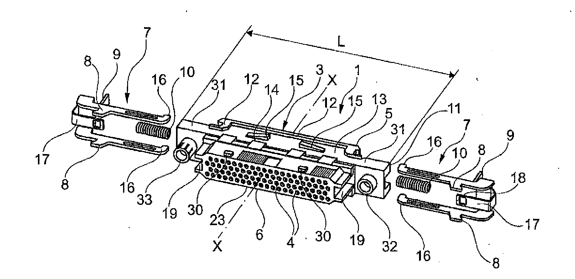
  • Multi-contact connector socket for rapid fastening to a panel, and associated installation and removal methods
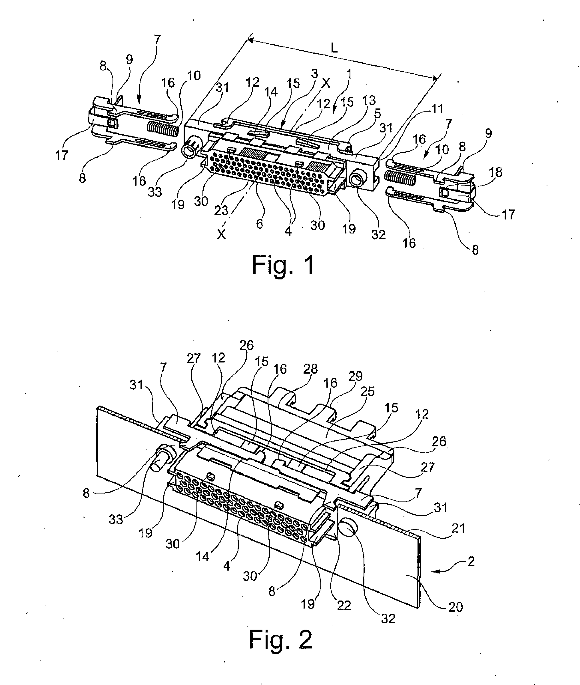
  • Multi-contact connector socket for rapid fastening to a panel, and associated installation and removal methods
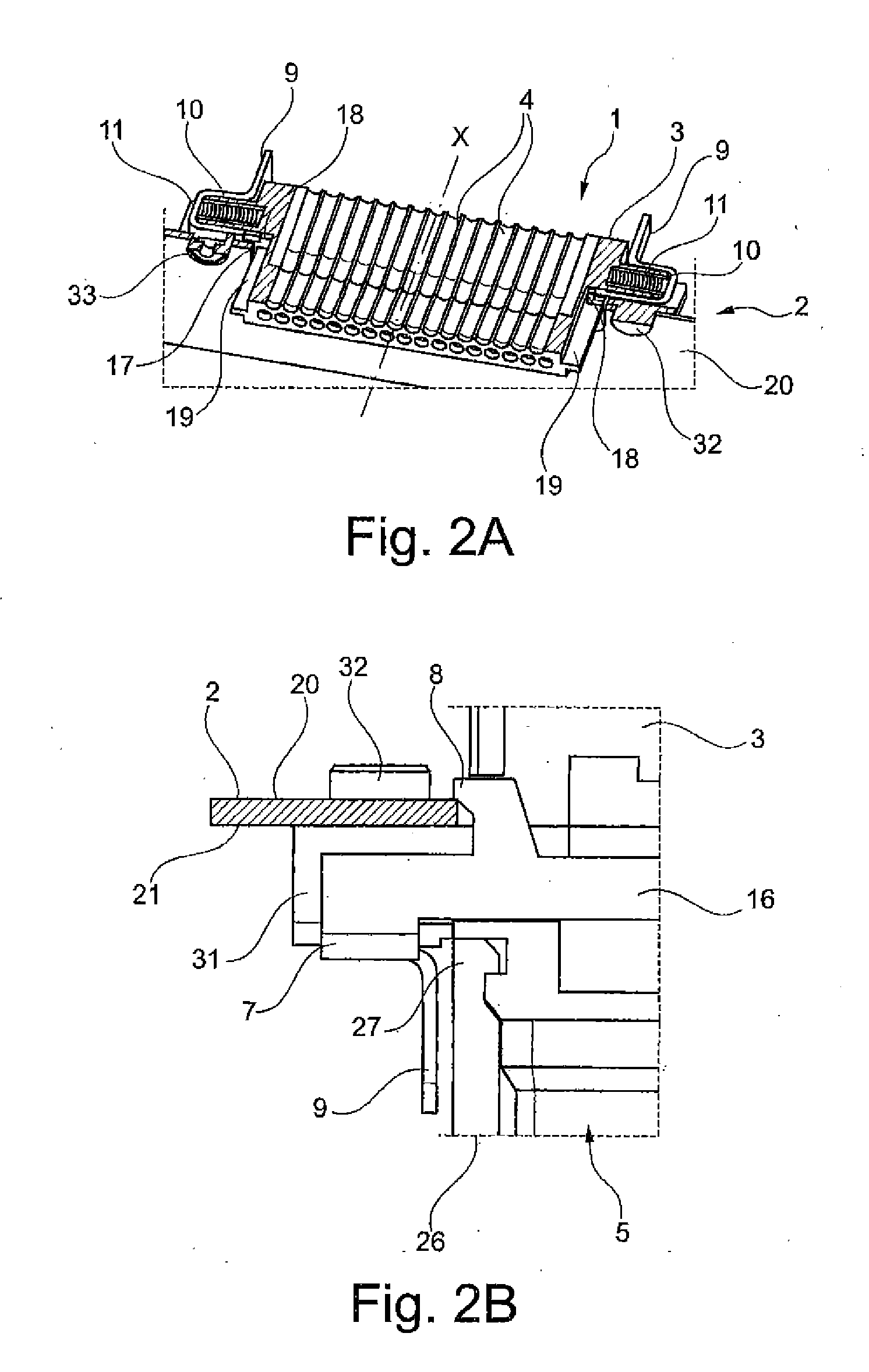
  • Multi-contact connector socket for rapid fastening to a panel, and associated installation and removal methods

Examples


second embodiment

[0121]FIG. 8 shows a multi-contact connector socket 1 of the invention. It is specified at this point has the figure does not show various portions of the housing 3 that are nevertheless present, such as the cells housing contacts, the pegs for locking to a locking cap, . . . . All the other elements that are in common and that are shown are given the same numerical references.

[0122]In this second embodiment, the connector socket 1 has a hooking part 7 including sliding hooking means 8m and stationary hooking means 8f that are stationary relative to the housing 3 and that extend transversely to the axis X of the housing 3 in a fastening position. The stationary hooking means 8f may comprise a single hook 8f over the full height of the housing 3 or a plurality of hooks, typically two hooks, that are distributed up the height. The stationary hooking means 8f may be made of the same material as the housing 3, i.e. they may be made integrally with the housing 3 while it is being molded....

first embodiment

[0124]For manual removal, the procedure is likewise as for the first embodiment, i.e. pressure is applied to the single tongue 9 to cause the sliding hooking means 8m to slide from the deployed position for fastening towards a retracted position for release. In contrast, the housing 3 is necessarily separated from the opening in the panel 2 from the side of the sliding hooking means 8m once they are in their retracted position for release and then, once the sliding means 8m are disengaged from the opening 22 and present beside the rear face 21 of the panel, it is possible for the stationary hooking means 8f to be disengaged from the opening in the panel 2.

[0125]For removal using a tool T, the procedure is likewise as in the first embodiment, except that the tool is inserted on one side only until the sole sliding hooking means 8m have disengaged the opening 22 in the panel 2, after which the stationary hooking means 8f are disengaged.

[0126]The invention is not limited to the above-d...


PUM

PropertyMeasurementUnit
Pressureaaaaaaaaaa
Shapeaaaaaaaaaa

Abstract

A connector socket has two hooking parts each having at least one hook to fasten to a housing, at least one hooking part is mounted on the housing; the two hooking parts move apart from each other when at least the slidable hooking part slides from a retracted position towards a deployed position; at least one tongue that is connected to the slidable hooking part to cause the hooking part to slide from a deployed position to a retracted position when an operator presses against the tongue; and at least one spring distinct from the hooking parts, each spring having one end connected to the housing and its other end connected to a corresponding slidable hooking part and exerting a thrust force thereon transversely to the axis of the housing, at least when in a deployed position and in the absence of pressure being applied on the corresponding tongue.

Description

FIELD OF THE INVENTION[0001]The present invention relates to a connector socket, in particular for a multi-contact connector, and that is for fastening to a panel.[0002]The invention also relates to associated installation and removal methods.BACKGROUND OF THE INVENTION[0003]Numerous means are already known for fastening a multi-contact connector socket to a panel. Of these means, mention may be made of fastener means constituted by two screw-and-nut systems, each of the two screws passing both through an opening formed in a respective lateral end of the housing of the socket and an opening formed in the panel beside a larger opening in which the socket is received.[0004]With certain multi-contact connectors, those screws can be used as polarizing means that make it possible to provide mutual locking between a male connector and a female connector. Although presently-existing means for fastening a multi-contact connector to a panel are effective, in particular when subjected to high...

Claims


Application Information

Patent Timeline
IPC IPC(8): H01R13/629H01R43/26
CPCH01R13/629H01R43/26H01R13/74Y10T29/49204
Inventor BECAVIN, PATRICEDEMARET, EMMANUEL
Owner RADIALL SA
Learn More