
Indexable circular cutting insert

a circular cutting insert and indexing technology, applied in the field of cutting inserts, can solve the problems of degrading not only the cutting edge, but the material in the cutting edge region

Active Publication Date: 2013-10-24
KENNAMETAL INC
View PDF19 Cites 14 Cited by
  • Summary
  • Abstract
  • Description
  • Claims
  • Application Information

AI Technical Summary

Benefits of technology

The subject invention is about a cutting insert with front and back positioning segments that allow for easy and accurate positioning in a toolholder. The front segments have centerlines that define radial angles, while the back segments have centerlines that also define radial angles. The front and back patterns of the segments are the same. The cutting insert is secured in the toolholder with a bottom wall that has matching receiving segments for easy assembly and disassembly. The technical effect of the invention is improved precision and efficiency in the cutting process.

Problems solved by technology

As a result, when the cutting edge on the first side was utilized, the cutting edge and the region adjacent to the cutting edge was subjected to high temperatures and extreme conditions, which tended to degrade not just the cutting edge, but the material in the region of the cutting edge.

Method used


Image

  • Indexable circular cutting insert
  • Indexable circular cutting insert
  • Indexable circular cutting insert

Examples


Embodiment Construction

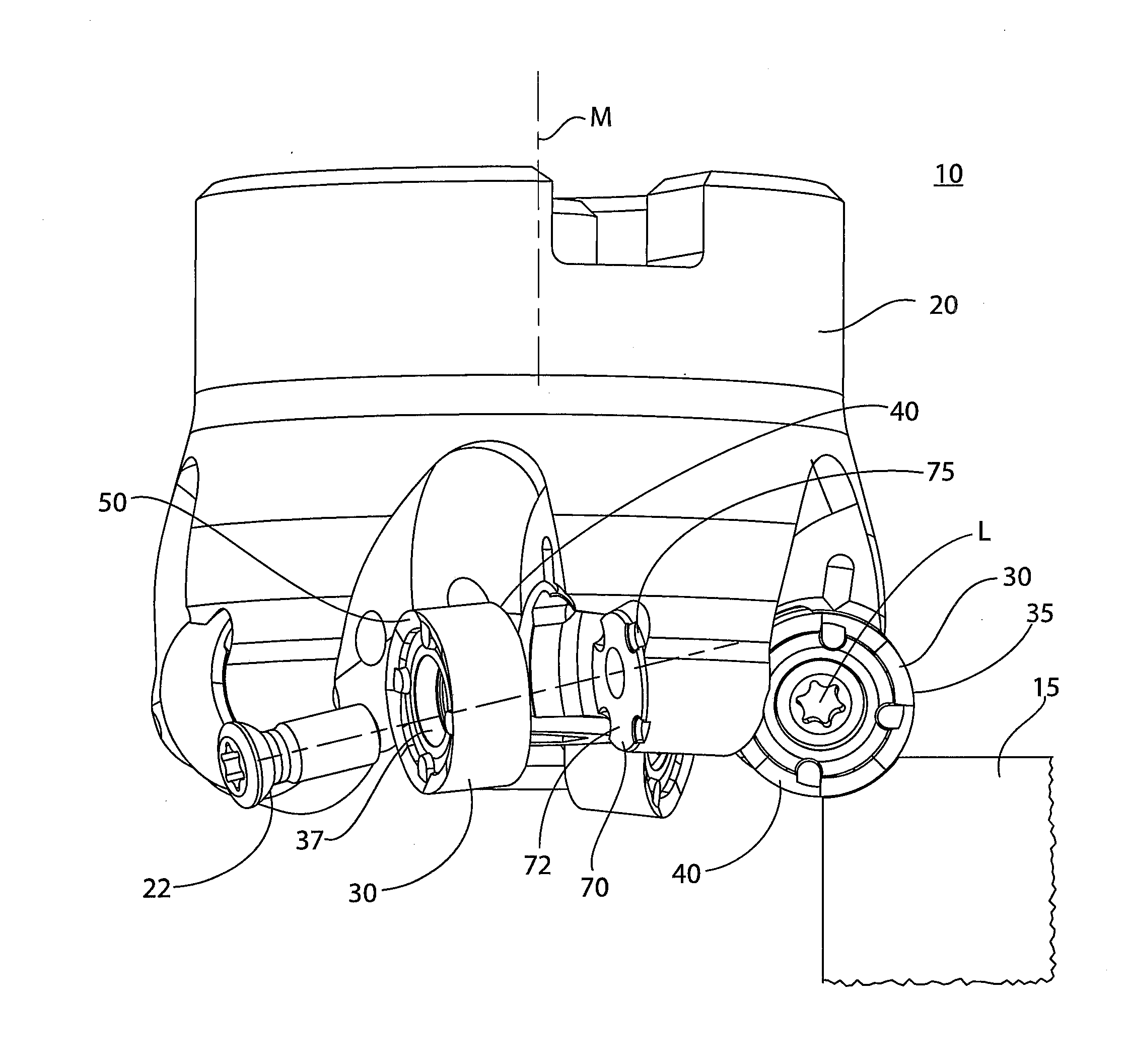
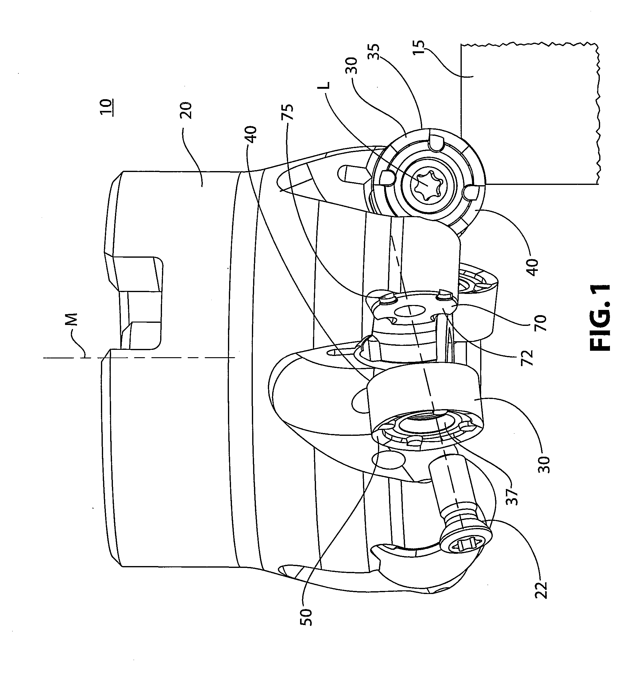
[0020]FIG. 1 illustrates a toolholder system 10 for cutting a workpiece 15, wherein there is relative rotation between a toolholder 20 and the workpiece 15. The toolholder system 10 is comprised of at least one cutting insert 30 and the toolholder 20. The toolholder 20 illustrated in FIG. 1 is a milling cutter that rotates about axis M.

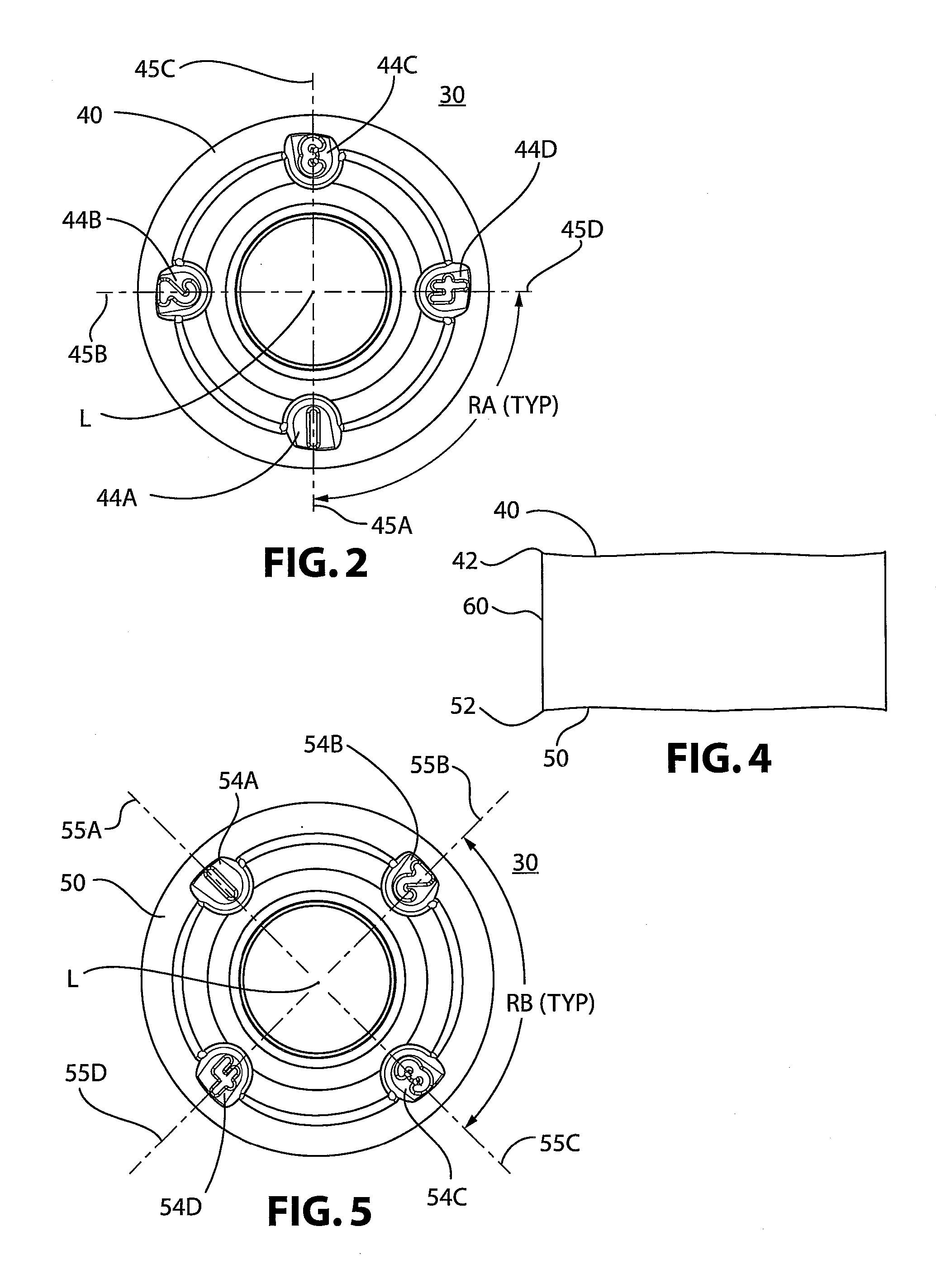
[0021]Directing attention to FIGS. 2-6, the cutting insert 30 has a body 35 with a front face 40, an opposing back face 50, and a side wall 60 therebetween. At the intersection of the sidewall 60 and the front face 40 is a front cutting edge 42. At the intersection of the sidewall 60 and the back face 50 is a back cutting edge 52. A plurality of positioning segments 44A-D, on the front face 40, have radial centerlines 45A-D extending from the longitudinal axis L, wherein the centerlines 45A-D of adjacent segments 44A-D define evenly-spaced radial angles RA about the central longitudinal axis L for indexing the cutting insert 30 within the toolholder 2...


PUM

PropertyMeasurementUnit
Angleaaaaaaaaaa
Angleaaaaaaaaaa
Angleaaaaaaaaaa

Abstract

An indexable, invertable cutting insert has radially-oriented positioning segments on a front face of the insert and radially-oriented positioning segments on the back face of the insert. The radially-oriented positioning segments are shifted on the front face relative to those on the back face such that, when the cutting insert is engaged within the toolholder, the cutting segment utilized on the front face will never be directly opposite the cutting segment utilized on the back face. A toolholder system is made up of the cutting insert and a toolholder capable of securing and indexing the cutting insert.

Description

BACKGROUND OF THE INVENTION[0001]1. Field of the Invention[0002]This invention relates to cutting inserts and is specifically directed to an invertable, indexable, circular cutting insert which, when inverted, is designed to engage a cutting region longitudinally shifted from a cutting region that may be utilized on the opposite side of the insert. The invention also relates to a toolholder system utilizing the subject cutting insert mounted within a toolholder, such as a milling cutter.[0003]2. Description of Related Art[0004]Milling cutters for cutting and shaping metal workpieces have been known for many years. Such milling cutters generally comprise a cylindrical cutting body having a plurality of insert seats spaced around the periphery of the body. Cutting inserts are mounted within the insert seats and the insert seats are oriented so that the inserts mounted therein will effectively cut a workpiece when a cutter body is rotated along a longitudinal axis. In one embodiment, c...

Claims


Application Information

Patent Timeline
IPC IPC(8): B23C5/22B23C5/02
CPCB23C5/06B23C2200/045B23C2200/081B23C2200/161B23C2200/168B23C2210/168B23C2210/66Y10T407/1924Y10T407/23Y10T407/1936Y10T407/2274Y10T407/20Y10T407/1964B23C5/202B23B27/1685B23C5/2239B23C5/2298B23C2200/363B23C5/22B23C2200/361B23B2200/168
Inventor MORRISON, LEWIS RAYMURPHY, HOWARDACCARDI, GIANFRANCOPROCOPIO, MARCOLIEBER, ANDREASSECULI, JUANMYLAVARAM NIKHILESH, KUMAR REDDY
Owner KENNAMETAL INC
Learn More