Display having pivot constraint function
a technology of constraint function and display, which is applied in the field of display, can solve the problems of user exerting violent force to adjust the rotation of the display, the volume of the display of the conventional electronic device is large, and the user's force is excessive, so as to reduce the operation steps, convenient adjustment, and effective economize the effect of the adjustment period
- Summary
- Abstract
- Description
- Claims
- Application Information
AI Technical Summary
Benefits of technology
Problems solved by technology
Method used
Image
Examples
first embodiment
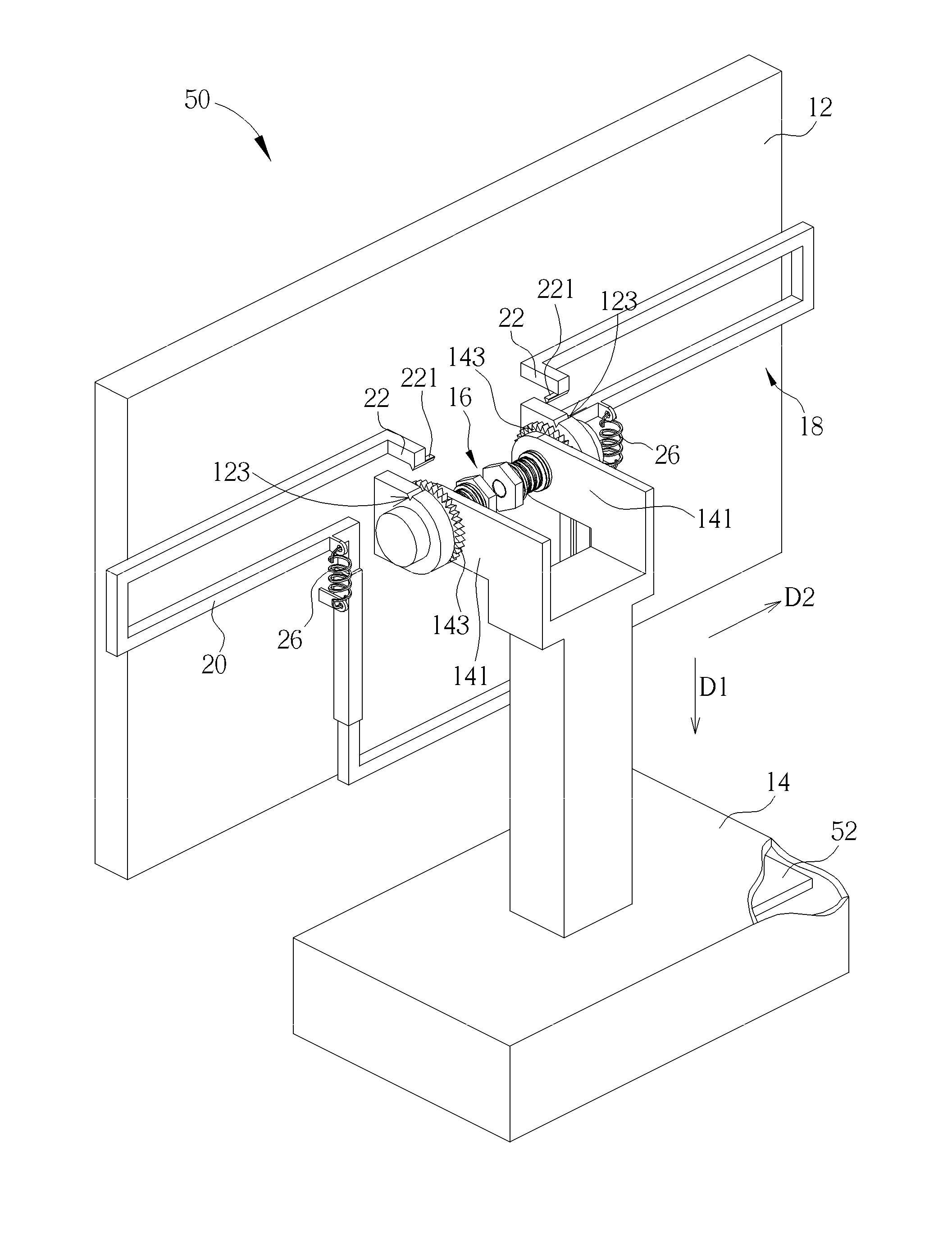
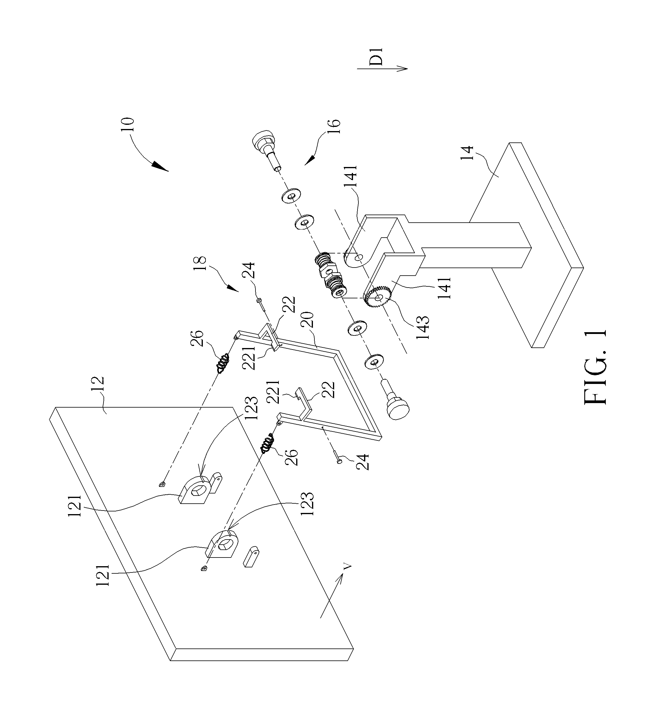
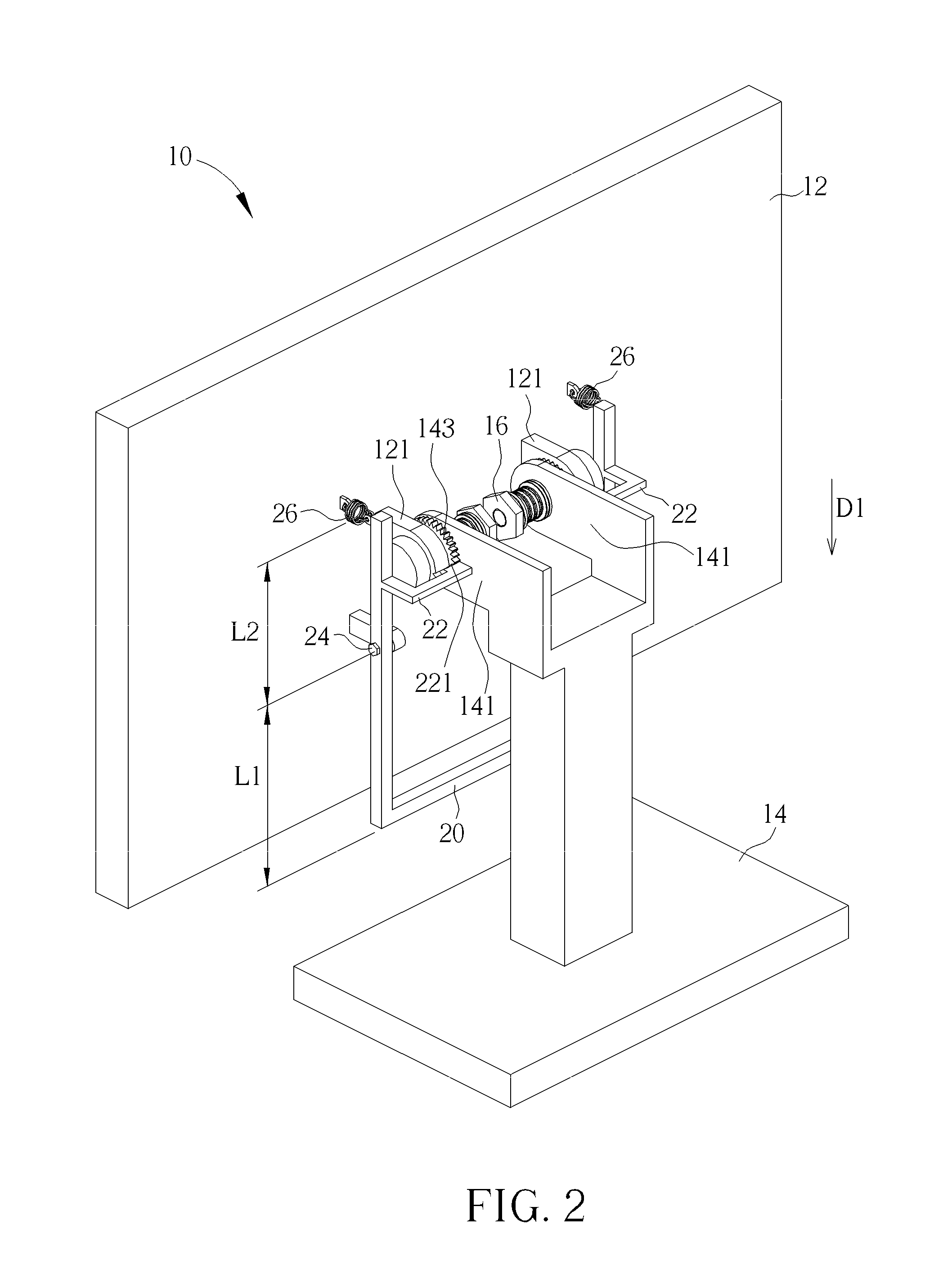
[0029]Please refer to FIG. 1. FIG. 1 is an exploded diagram of a display 10 according to the present invention. The display 10 can be a displaying screen, a touch screen or an All-in-one computer. The display 10 has a function to constrain its panel rotation. As shown in FIG. 1, the display 10 includes a panel 12, a supporter 14, a pivot mechanism 16 and a constraint mechanism 18. The panel 12 can be a display screen or a board holder. A view angle of the display screen can be adjusted and fixed at any position. The board holder can be utilized to hold an object for performance.
[0030]The panel 12 and the supporter 14 can respectively include two first bridging components 121 and two second bridging components 141 for connecting to the pivot mechanism 16. The pivot mechanism 16 is disposed between the first bridging component 121 and the second bridging component 141. A rotation angle of the panel 12 relative to the supporter 14 can be adjusted via the pivot mechanism 16. For fixing ...
second embodiment
[0043]The first bridging component 121, the second bridging component 141 and the contacting portion 22 of the second embodiment have smooth surfaces. The friction gasket 32 disposed on the contacting portion 22 can increase static friction between the first bridging component 121, the second bridging component 141 and the contacting portion 22. When the contacting portion 22 tightly contacts the first bridging component 121 and the second bridging component 141 via the friction gaskets 32 and the resilient component 26, a value of the static friction can be designed as being substantially greater than resultant on the supporter 14 that is applied by a weight of the panel 12 via the pivot mechanism 16, so as to prevent the panel 12 from shaking or swaying effectively.
[0044]Please refer to FIG. 5 to FIG. 7. FIG. 5 is an exploded diagram of a display 40 according to a third embodiment of the present invention. FIG. 6 and FIG. 7 respectively are diagrams of the display 40 in different ...
third embodiment
[0046]The constraint mechanism 18 of the display 40 of the third embodiment utilizes the structural engagement to lock and to unlock the pivot mechanism 16. As the display 40 is at the initial state, the pivot mechanism 16 is locked by the constraint mechanism 18, and the panel 12 can not rotate relative to the supporter 14. For unlocking the constraint mechanism 18, the protruding part of the body 20 (the part protrudes from the right and the left boundary of the panel 12, or protrudes from the upper and the low boundary of the panel 12) can be pushed along a direction opposite to the first direction, so as to separate the third engaging portion 221 of the contacting portion 22 from the first engaging portion 123 and the second engaging portion 143. As shown in FIG. 7, the view angle of the panel 12 can be adjusted according to actual demand, and the resilient component 26 is extended to store the resilient recovering force. After the view angle of the panel 12 is determined, the e...
PUM
 Abstract
Description
Claims
Application Information
 - R&D
- Intellectual Property
- Life Sciences
- Materials
- Tech Scout
- Unparalleled Data Quality
- Higher Quality Content
- 60% Fewer Hallucinations
Browse by: Latest US Patents, China's latest patents, Technical Efficacy Thesaurus, Application Domain, Technology Topic, Popular Technical Reports.
© 2025 PatSnap. All rights reserved.Legal|Privacy policy|Modern Slavery Act Transparency Statement|Sitemap|About US| Contact US: help@patsnap.com


