
Vibratory feeder for conveying components

a feeder and vibrator technology, applied in conveyors, conveyors, jigging conveyors, etc., can solve the problems of vibration module also generating noise, unwanted motion of components,

Active Publication Date: 2013-10-17
ASMPT SINGAPORE PTE LTD
View PDF4 Cites 34 Cited by
  • Summary
  • Abstract
  • Description
  • Claims
  • Application Information

AI Technical Summary

Benefits of technology

The invention is a vibration feeding apparatus that can provide both rotary and linear vibration to a receptacle. This allows for more efficient and better control over the vibration process. The apparatus includes two linear motors that are spaced from each other and have coils aligned parallel to each other. By driving the motors at different modes, the apparatus can provide either rotary or linear vibration as needed. This design solves the problems of previous vibration feeding devices that could only provide rotary vibration.

Problems solved by technology

Undesirable frequency components will cause unwanted motion of the components being transferred using the vibrator module.
It may also generate noise from abrupt changes in the driving signal source.
Apart from the multiple frequency components generated by the vibrator module, the vibrator module also generates noise as a result of abrupt changes in force inherent in a square waveform.
Reliability of the piezoelectric element is thus a major problem for the vibratory feeding apparatus when it is operated in heavy volume production.
Also, the cost of piezoelectric elements is usually higher than for solenoids.
Apart from nonlinear forces and lack of reliability of prior art vibration actuators, the designs of vibrator modules are usually limited to only linear or rotary agitation.
Further, there is a risk of jamming between the two systems when the two systems separately vibrate.

Method used


Image

  • Vibratory feeder for conveying components
  • Vibratory feeder for conveying components
  • Vibratory feeder for conveying components

Examples


Embodiment Construction

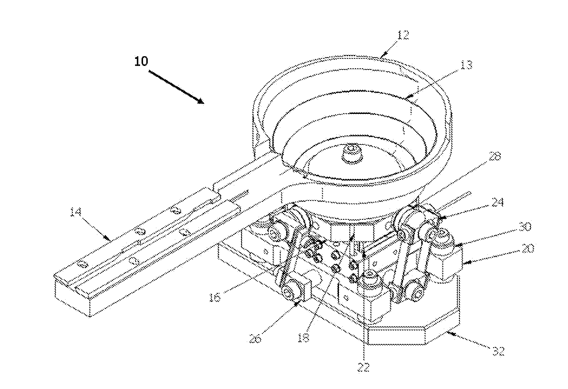
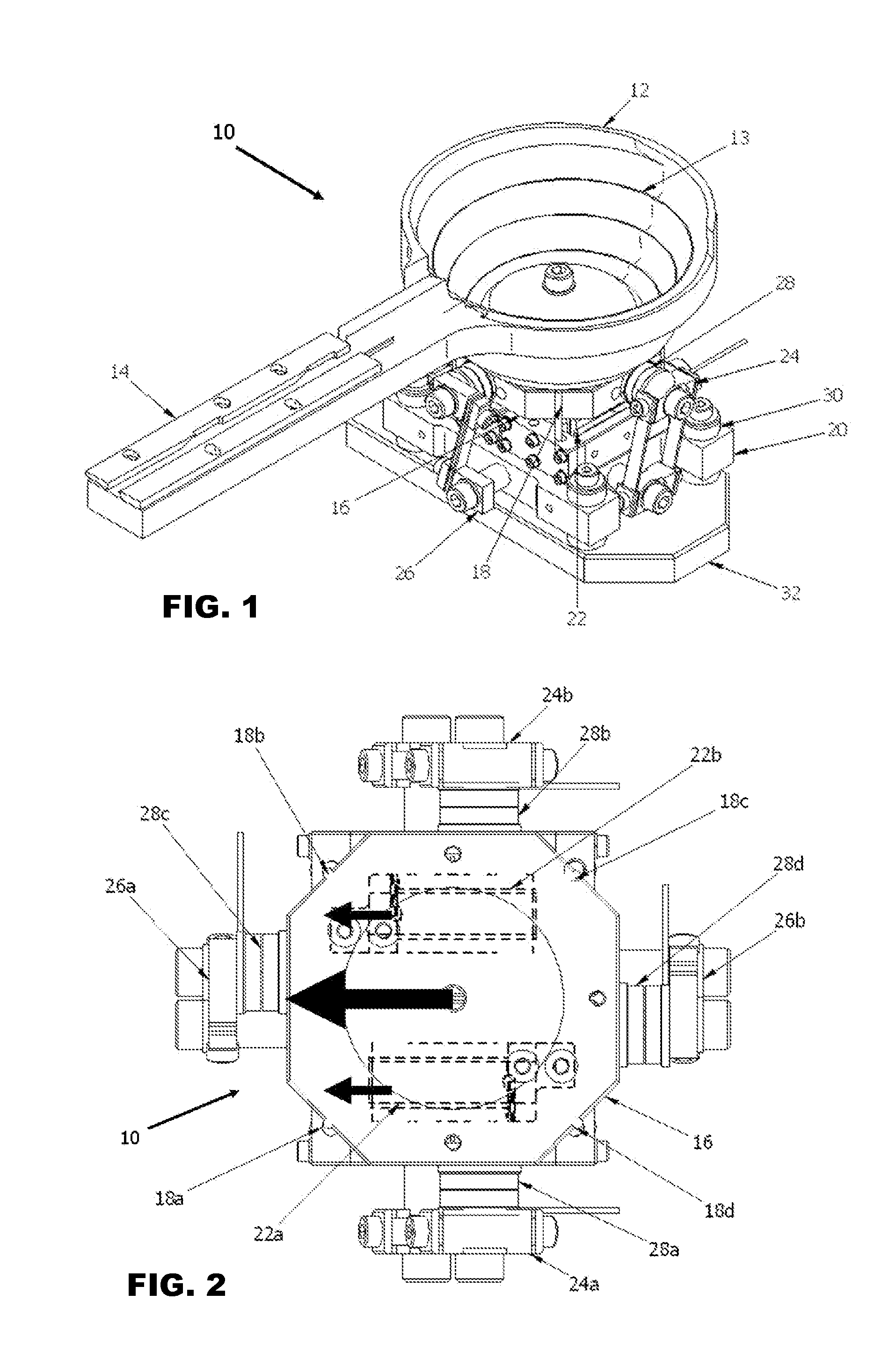
[0020]FIG. 1 is an isometric view of the vibration feeding apparatus 10 according to the preferred embodiment of the invention.

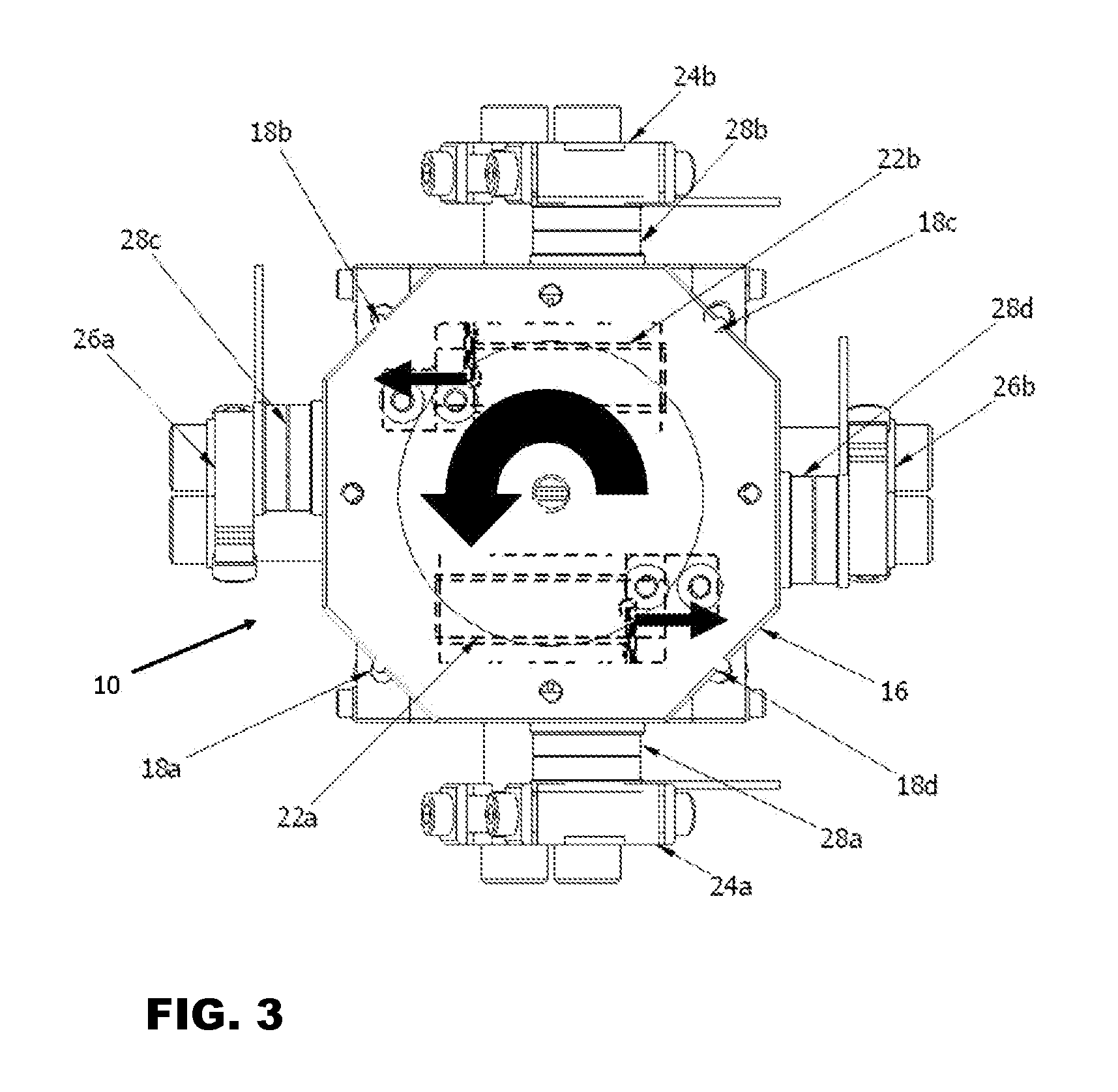
[0021]This vibration feeding apparatus 10 includes a receptacle for holding and conveying components, which may comprise a vibration feeding bowl 12 having an internal spiral track 13 and a linear vibration feeding track 14. It uses first and second linear motors 22a, 22b, such as voice coil motors, as actuators for driving the apparatus 10. The vibration feeding apparatus 10 generally comprises the following major parts, namely: a vibrator top plate 16, springs 24, 26, linear motors 22a, 22b and a vibration isolation base 20. In order to make the total height profile as low as possible, the first and second linear motors 22a, 22b are located and sandwiched between the vibrator top plate 16 and the vibration isolation base 20. The first and second linear motors 22a, 22b are spaced from each other and respective coils of the linear motors 22a, 22b are aligned...


PUM


Abstract

A vibration feeding apparatus comprises a receptacle for holding and conveying components, and first and second linear motors coupled to the receptacle. The first and second linear motors are spaced from each other and have respective coils that are aligned parallel to each other. The first and second linear motors are operative to be driven at a first operation mode whereby to impart rotary vibration to the receptacle, and at a second operation mode whereby to impart linear vibration to the receptacle.

Description

FIELD OF THE INVENTION[0001]The invention relates to a feeding apparatus for transporting components, and in particular to a feeding apparatus which transports components using mechanical agitation.BACKGROUND AND PRIOR ART[0002]A vibratory feeding apparatus may comprise a container in the form of a rotary vibration bowl and a linear feeder in the form of a vibration track. They can be found in industry for conveying and orientating components, for instance electronic components, which are sorted from a pool of randomly oriented components during mass production. They are different from belt conveyers in that vibratory feeding apparatus use small vibrations to transfer components in a step-wise manner. Due to its simplicity and lack of moving mechanical parts, the vibratory feeding apparatus can provide a cleaner and more reliable way of conveying small components. Thus, there are large numbers of vibratory feeding apparatus developed for conveying small components in different indus...

Claims


Application Information

Patent Timeline
IPC IPC(8): B65G27/02B65G27/08B65G27/24
CPCB65G27/02B65G27/24
Inventor CHOY, PING KONGYUNG, CHUNG SHEUNGWONG, HO CHILAU, CHUNG YIN
Owner ASMPT SINGAPORE PTE LTD
Learn More