
Clamping mechanism

a technology of clamping mechanism and roof box, which is applied in the direction of transportation and packaging, vehicle components, supplementary fittings, etc., can solve the problems of difficult to reach the clamping mechanism when mounted on the roof box, and achieve the effect of the roof box clamping mechanism

Inactive Publication Date: 2013-10-10
HUBCO AUTOMOTIVE
View PDF21 Cites 11 Cited by
  • Summary
  • Abstract
  • Description
  • Claims
  • Application Information

AI Technical Summary

Benefits of technology

The invention is a roof box that can be easily attached to a roof rack using a clamping mechanism. This makes it easy to access and remove the roof box without having to open it up. The roof box is also designed to protect the items inside from weather and theft. The technical effects of the invention are ease of access, convenience, and protection for stored items.

Problems solved by technology

One drawback noted above of roof box designs is that the roof box clamping mechanism is achieved via one or more mechanisms that can only be reached via the interior of the roof box.
Drawbacks include having to remove the roof box contents in order to access the clamping mechanism and remove the roof box form the roof racks.
Secondly, the clamping mechanism when mounted on a vehicle can be difficult to reach, particularly if the vehicle has a relatively high ground clearance.

Method used


Image

  • Clamping mechanism
  • Clamping mechanism
  • Clamping mechanism

Examples


working examples

[0075]The invention is now described with reference to a detailed description of various embodiments of the roof box of the present invention.

[0076]Referring to FIG. 1, the roof box, generally indicated by arrow 1, when closed has a styled, aesthetically appealing shape. The roof box 1 includes a top section 2 and a base section 3. The roof box 1 includes a lock assembly 4. No features of the clamping assembly are visible from the exterior of the roof box 1 when viewed from above as in FIG. 1.

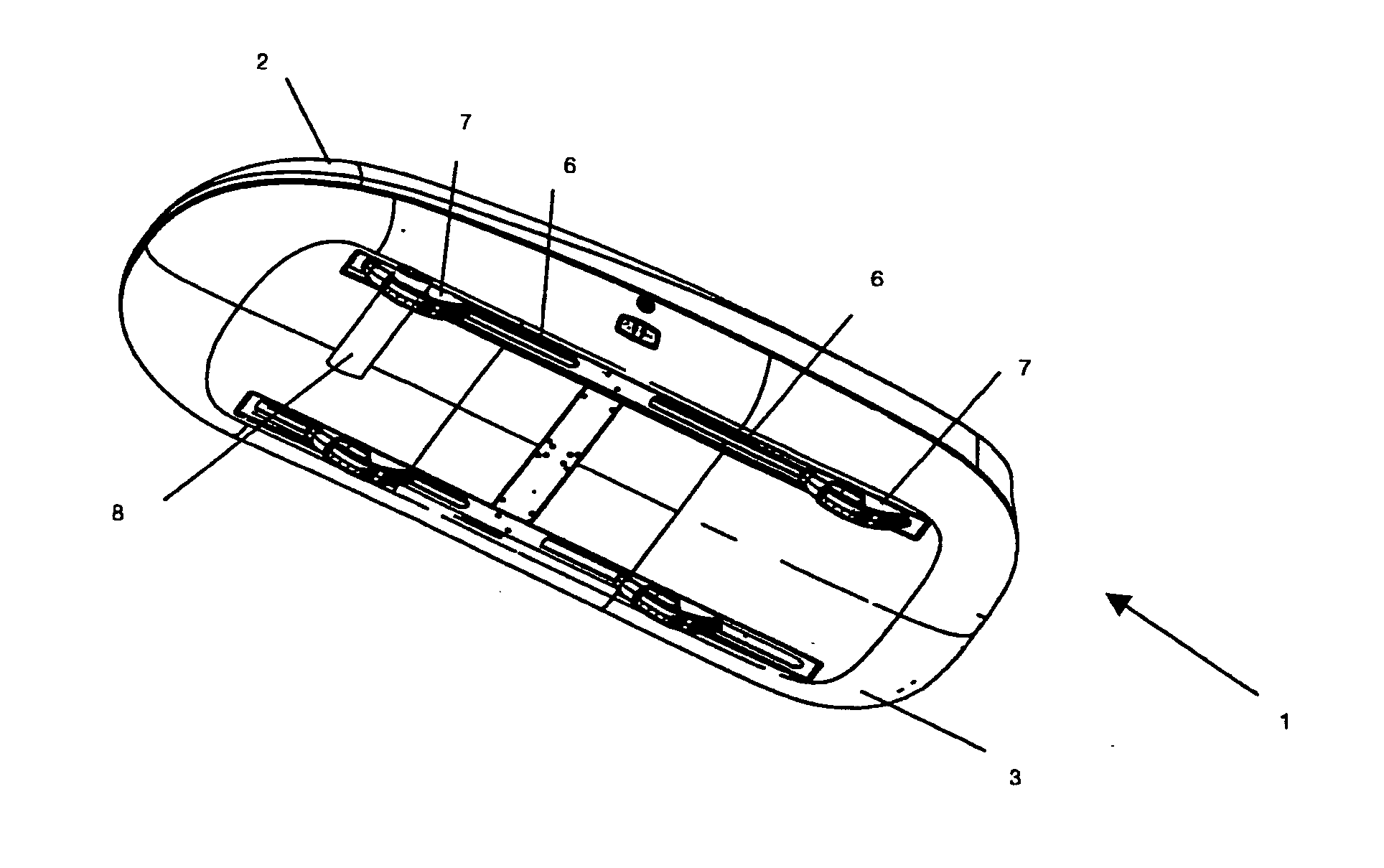
[0077]FIG. 2 illustrates the roof box 1 in assembled mode when viewed from below. The box 1 still includes the top section 2 and base section 3. The lock assembly 4 is also still visible. Newly viewed in FIG. 2 is the clamping assembly handle 5 used to urge clamping and removal of the roof box from the vehicle roof racks (not shown). The underside of the roof box 1 base section 3 includes four slots 6 positioned to approximate the roof rack position on a vehicle roof. It should be appreciated t...


PUM


Abstract

A roof box 1 for mounting to a vehicle is described. The roof box 1 includes a clamping mechanism that enables the roof box 1 to be secured to a vehicle via one or more externally accessed actuating handles 5. A crossbar interchangeable clamp shape is also described for linking an accessory item such as a roof box 1 to a roof rack cross bar.

Description

TECHNICAL FIELD[0001]The invention relates to a clamping mechanism. More specifically, the invention relates to a clamping mechanism used to mount a vehicle roof box to vehicle roof rack crossbars.BACKGROUND ART[0002]Roof boxes are well known and commercialised worldwide. Roof boxes comprise a container mountable to a roof area of a vehicle and are adapted to store luggage, cargo and / or other objects (e.g. sporting equipment such as skis and snowboards). Typically, the roof box is made up of a bottom section for mounting to the roof area of a vehicle and a top section movable relative to the bottom section for opening and closing the roof box. Roof boxes may be preferable to an open roof rack accessory holder since they protect the items stored inside from exposure to adverse weather and environmental conditions as well as provide robust protection against theft and vandalism.[0003]There are a wide range of different styles, features and prices available although roof boxes have bec...

Claims


Application Information

Patent Timeline
Patent Type & Authority Applications(United States)
IPC IPC(8): B60R9/055
CPCB60R9/058B60R9/055
Inventor HUBBARD, PETER DOUGLASROBERTSON, BRUCE JOHN
Owner HUBCO AUTOMOTIVE
Learn More