
Light source device for vehicle

a technology for light source devices and vehicles, applied in lighting support devices, lighting and heating apparatuses, instruments, etc., can solve the problems of cumbersome adjustment of the light emission angle of point light sources, and achieve the effect of improving the visibility of ligh

Inactive Publication Date: 2013-10-03
TOYOTA JIDOSHA KK +1
View PDF2 Cites 15 Cited by
  • Summary
  • Abstract
  • Description
  • Claims
  • Application Information

AI Technical Summary

Benefits of technology

The invention is a light source device for vehicles that improves visibility without the need for complex adjustments. The light sources are placed on the windscreen in a way that they match the shape of the area, making them easier for the driver to see. This improves information transmission and efficiency without requiring excessive adjustment.

Problems solved by technology

However, according to JP-A-2008-13163 and JP-A-2008-189201, cumbersome adjustment of the light emission angle of the point light sources is required to linearly project the virtual image on the windshield.

Method used


Image

  • Light source device for vehicle
  • Light source device for vehicle
  • Light source device for vehicle

Examples


Embodiment Construction

[0020]Description is hereinafter made of an embodiment of a light source device for a vehicle according to the present invention with reference to the drawings. It should be noted that the present invention is not limited by the embodiment.

[0021]In the following, a case where a light source panel according to this embodiment is incorporated in a right-hand drive vehicle and is used in an information transmission system for a vehicle that conveys information to the driver by reflecting a virtual image that is formed by light on the windshield glass is described as an example.

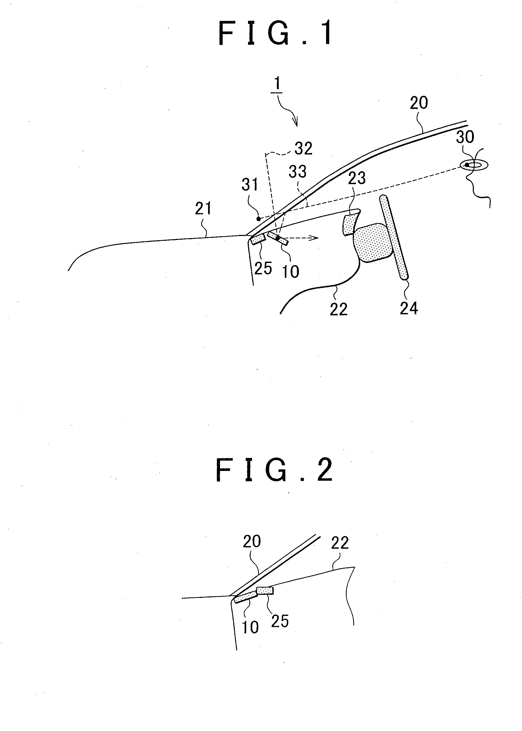
[0022]FIGS. 1 and 2 are views, each of which illustrates an example of the installation position of a light source panel. In FIGS. 1 and 2, reference numeral 1 indicates a vehicle, reference numeral 10 indicates a light source panel, reference numeral 20 indicates a front windshield glass, reference numeral 21 indicates a bonnet, reference numeral 22 indicates an instrument panel, reference numeral 23 indicates a...


PUM


Abstract

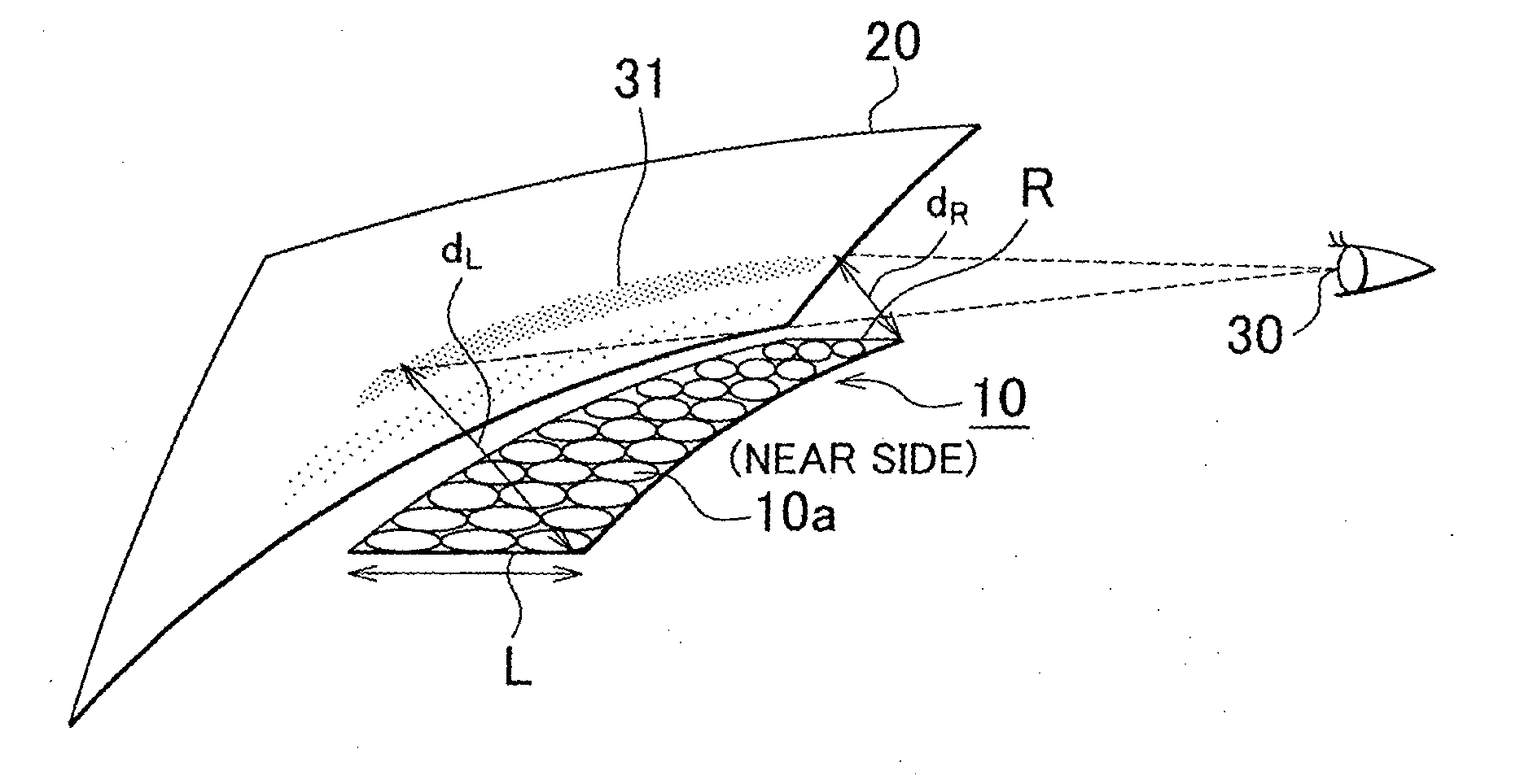
The driver side of a light source panel is curved in a concave configuration which conforms with the curvature (curve) of the cross-section of the area of a front windshield glass, in which a virtual image is displayed. Individual light sources are arranged in the light source panel in a curved configuration which conforms with the curvature (curve) of the cross-section of the area of the front windshield glass, in which the virtual image is displayed.

Description

BACKGROUND OF THE INVENTION[0001]1. Field of the Invention[0002]The present invention relates to a light source device for a vehicle.[0003]2. Description of the Related Art[0004]Each of Japanese Patent Application Publication No. 2008-13163 (JP-A-2008-13163) and Japanese Patent Application Publication No. 2008-189201 (JP-A-2008-189201) discloses a visual recognition assistance device for a vehicle, in which a plurality of point light sources are linearly arranged in the vicinity of a boundary between an instrument panel and a windshield, and which linearly projects a virtual image on the windshield.[0005]Other related art documents include Japanese Patent Application Publication No. 2008-197403 (JP-A-2008-197403), Japanese Patent Application Publication No. 2002-287076 (JP-A-2002-287076), Japanese Patent Application Publication No. 2002-274216 (JP-A-2002-274216), and Japanese Patent Application Publication No. 2003-54334 (JP-A-2003-54334). JP-A-2008-197403 discloses a headup display...

Claims


Application Information

Patent Timeline
Patent Type & Authority Applications(United States)
IPC IPC(8): F21S8/10
CPCB60K35/00B60K2350/2052B60K2350/2065F21S48/00G02B27/01G02B2027/011B60K2350/965B60K35/29B60K2360/191B60K35/28B60K2360/31B60K2360/334B60K35/60B60K37/20B60K35/22B60K35/40F21S43/00
Inventor HATAKEYAMA, YOSHIYUKIKAWAMATA, SHINYAIGUCHI, SEI
Owner TOYOTA JIDOSHA KK
Learn More