
Stator for an electrical machine

a technology for stators and electrical machines, which is applied in the direction of dynamo-electric machines, synchronous machines with stationary armatures and rotating magnets, and manufacturing dynamo-electric machines. it can solve the problems of compromising the alignment of stator elements, complicating the assembly process, and tolerating the geometry and dimensions of bridges and poles, so as to reduce reluctance, reduce flux leakage, and reduce air gap

Active Publication Date: 2013-09-26
DYSON TECH LTD
View PDF7 Cites 40 Cited by
  • Summary
  • Abstract
  • Description
  • Claims
  • Application Information

AI Technical Summary

Benefits of technology

The patent text describes a design for an electrical machine stator that has a high fill-actor and is easy to assemble. By using c-shaped cores and molded bridges, the stator elements are aligned accurately and a small air gap is achieved. The bridges are securely attached to the stator poles and the rotor is then aligned relative to the stator. The design also reduces reluctance and provides better cooling for the coil. A sensor can be accurately positioned within the stator for accurate measurement of the rotor position. Overall, this design simplifies the assembly process and achieves improved performance of the electrical machine.

Problems solved by technology

If the bridges were provided as prefabricated components that are secured to the poles, tolerances in the geometry and dimensions of the bridges and the poles may compromise the alignment of the stator elements.
In contrast, if the stator elements were provided as distinct elements, it would be necessary to secure and align each of the stator elements and the rotor simultaneously, which would complicate the assembly process.

Method used


Image

  • Stator for an electrical machine
  • Stator for an electrical machine
  • Stator for an electrical machine

Examples


Embodiment Construction

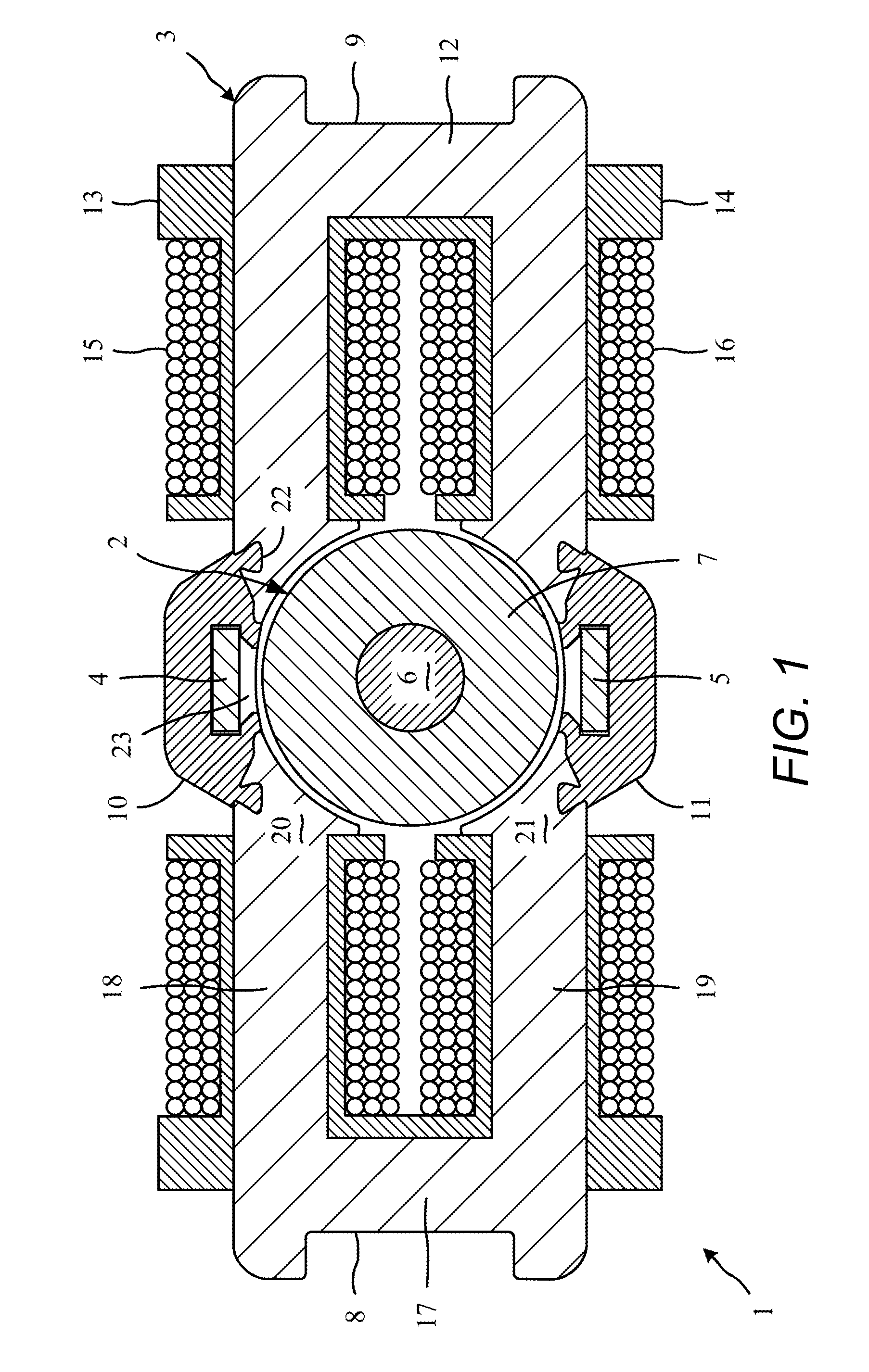
[0019]The electrical machine 1 of FIG. 1 comprises a rotor 2, a stator 3, a Hall-effect sensor 4 and a temperature sensor 5.

[0020]The rotor 2 comprises a shaft 6 to which a four-pole permanent magnet 7 is secured.

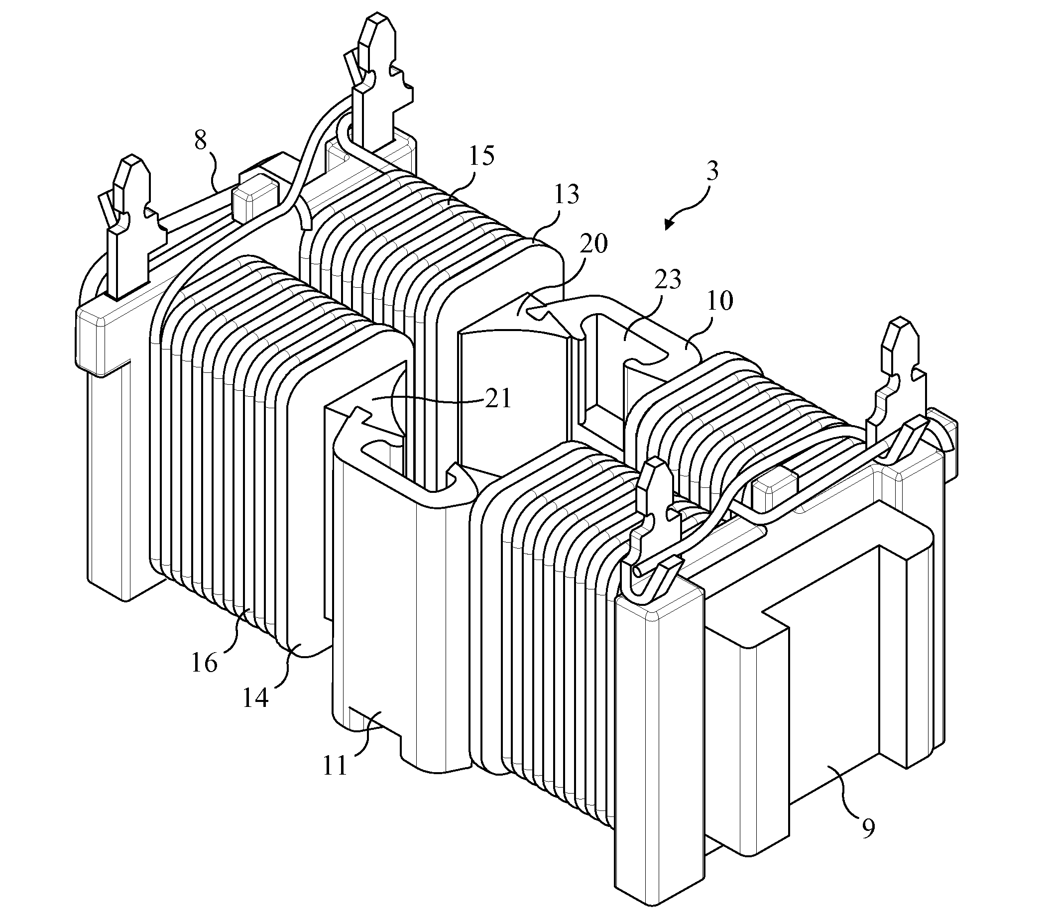
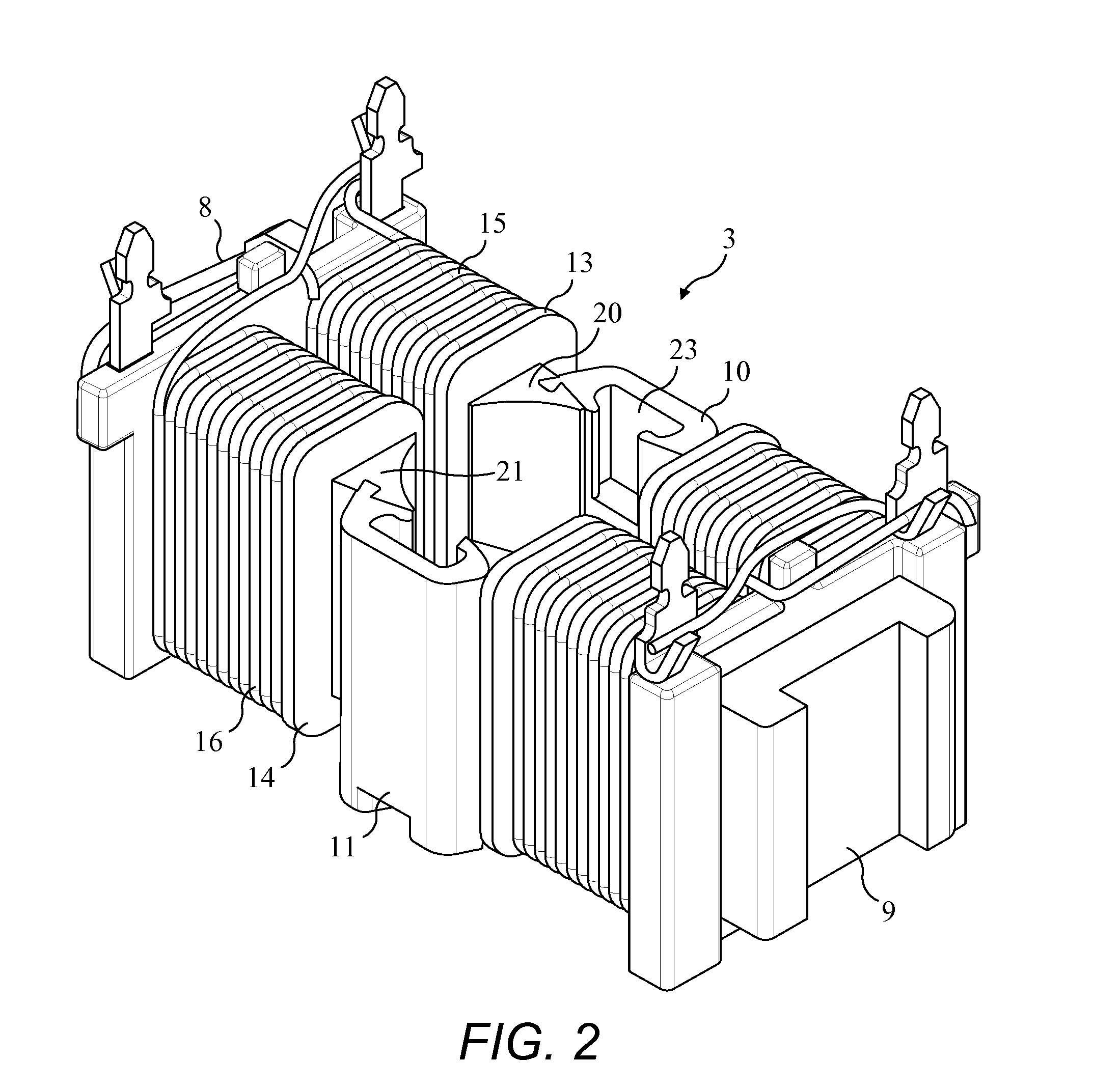
[0021]The stator 3, which is additionally illustrated in FIG. 2, comprises two stator elements 8,9 secured together by two bridges 10,11.

[0022]Each stator element 8,9 comprises a core 12, a pair of bobbins 13,14, and a pair of coils 15,16.

[0023]The core 12 comprises a plurality of laminations of a magnetic material, e.g. electrical steel. The core 12 is c-shaped and comprises a back 17 and two arms 18,19 that extend from opposite ends of the back 17. Each arm 18,19 extends toward the rotor 2 and has a free end that defines a pole 20,21.

[0024]Each bobbin 13,14 surrounds a respective arm 18,19 of the core 12, and each coil 15,16 is wound onto a respective bobbin 13,14. A single wire may be used for both coils 15,16 of each stator element 8,9. Alternatively, separate wires may...


PUM


Abstract

A stator includes a plurality of stator elements, each stator element comprising a c-shaped core having two poles. Each pole of each stator element is secured to a pole of an adjacent stator element by a bridge formed of a non-magnetic material moulded onto the poles.

Description

REFERENCE TO RELATED APPLICATION[0001]This application claims priority of United Kingdom Application No. 1205147.0 filed Mar. 23, 2012, the entire contents of which are incorporated herein by reference.FIELD OF THE INVENTION[0002]The present invention relates to a stator for an electrical machine, and to an electrical machine incorporating the same.BACKGROUND OF THE INVENTION[0003]The stator of a four-pole electrical machine may comprise two c-shaped cores arranged on opposite sides of the rotor. In employing c-shaped cores, a relatively high fill-factor may be achieved for the stator. Additionally, winding the coils onto the cores is generally easier in comparison to that for a single-piece core.[0004]The air gap between the rotor and the stator is ideally as small as possible so as to reduce reluctance. On the other hand, the air gap must be sufficiently large such that, at the tolerance limit, the rotor is free to rotate without contacting the stator. Tolerances in the alignment ...

Claims


Application Information

Patent Timeline
IPC IPC(8): H02K1/18
CPCH02K1/141H02K21/14H02K1/18H02K15/022H02K1/145H02K1/223H02K37/08
Inventor KING, GARYTEDEN, NICHOLAS RICHARD BASIL
Owner DYSON TECH LTD
Learn More