


Quick Research
Generate reliable direction feasibility study reports for your R&D in just a few steps.

Technical Q&A
Discover and master advanced knowledge NOW. Basics, ideas, possibilities, all at once.

Find Solutions
As an expert in R&D theories, this can generate solutions to your technical problems instantly.

Evaluate Feasibility
Analyze your overall solution with one click, know your potential R&D risks in advance.

Monitor Landscape
Get weekly tech updates, stay abreast of the latest tech innovations and key insights.
Photovoltaic apparatus, maximum power point tracking control method and computer program in the same, and moving body including the same
a technology of photovoltaic equipment and tracking control, which is applied in the direction of dynamo-electric converter control, process and machine control, instruments, etc., can solve the problems of high power consumption in the control system and difficulty in quick mppt control, and achieve fast and efficient maximum power point tracking control, eliminate the effect of shad
- Summary
- Abstract
- Description
- Claims
- Application Information
AI Technical Summary
Benefits of technology
Problems solved by technology
Method used
Image


Examples
embodiment 1
[0108]By referring to FIG. 11 to FIG. 16, a description will be given of a photovoltaic module 10 included in a photovoltaic apparatus 1 (see Embodiment 2) according to the present invention as Embodiment 1.
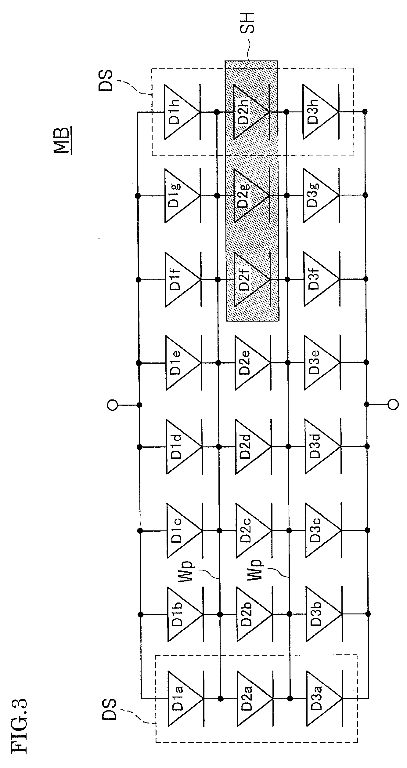
[0109]FIG. 11 is a pattern diagram illustrating a coupling condition of a photovoltaic element 11 in the photovoltaic module 10 applied to Embodiment 1 of the present invention.
[0110]In the photovoltaic module 10, a plurality of series portions 12 are coupled in parallel. The series portion 12 includes a plurality of photovoltaic elements 11 coupled in series. In the plurality of the series portions 12, the respective photovoltaic elements 11 coupled in the same straight row are coupled in parallel.
[0111]The photovoltaic module 10 is preferred to employ a distributed arrangement where a layout pattern of the photovoltaic elements 11 is different from the arrangement in the equivalent circuit. With this configuration, the photovoltaic module 10 employs a distributed arrangement as...
embodiment 2
[0147]By referring to FIG. 17 to FIG. 19, descriptions will be given of the photovoltaic apparatus 1 according to this embodiment, a maximum power point tracking control method in the photovoltaic apparatus 1, and a computer program that makes a computer execute the maximum power point tracking control in the photovoltaic apparatus 1. Here, the photovoltaic module 10 included in the photovoltaic apparatus 1 is the photovoltaic module 10 described in Embodiment 1.
[0148]FIG. 17 is a block diagram illustrating an overall configuration of the photovoltaic apparatus 1 according to Embodiment 2 of the present invention mainly using functional blocks.
[0149]FIG. 18 is a flowchart illustrating an operation process in a tracking control device 20 that constitutes a main portion of the photovoltaic apparatus 1 illustrated in FIG. 17.
[0150]FIG. 19 is a graph illustrating a state of maximum power point tracking control in the tracking control device 20 that constitutes the main portion of the ph...
embodiment 2-1
[0151]First, as (Embodiment 2-1), by referring mainly to FIG. 17 (the functional blocks), a description will be given of the photovoltaic apparatus 1 (here, FIG. 19 is referred as necessary).
[0152]The photovoltaic apparatus 1 according to this embodiment includes a photovoltaic module 10 and a tracking control device 20. In the photovoltaic module 10, a plurality of series portions 12 with a plurality of photovoltaic elements 11 coupled in series are coupled in parallel, and the photovoltaic elements 11 coupled in the same straight row among the plurality of series portions 12 are coupled parallel to one another. The tracking control device 20 performs a maximum power point tracking control (MPPT control) at the output of the photovoltaic module 10.
[0153]The photovoltaic module 10 includes a temperature sensor 18 that detects a real panel temperature RTp that is a panel temperature Tp when the photovoltaic module 10 is operating.
[0154]The tracking control device 20 includes, as basi...
PUM
 Abstract
Description
Claims
Application Information
 - R&D Engineer
- R&D Manager
- IP Professional
- Industry Leading Data Capabilities
- Powerful AI technology
- Patent DNA Extraction
Browse by: Latest US Patents, China's latest patents, Technical Efficacy Thesaurus, Application Domain, Technology Topic, Popular Technical Reports.
© 2024 PatSnap. All rights reserved.Legal|Privacy policy|Modern Slavery Act Transparency Statement|Sitemap|About US| Contact US: help@patsnap.com